Rebuilding the Holley NH Carburetor for your Model T Ford
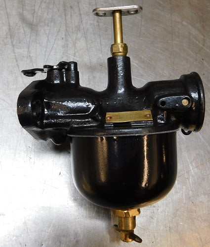
The most common of all Model T carburetors is the Holley NH. It was first used in the 1920 model year, the primary carburetor supplied for all Model T Fords and TT fords. This advertisement shows the earliest version used by Ford which has a so – called “straight thru” venturi throat arrangement. It also uses the earlier style float bowl with side drain.
In this issue we will examine the simplest (and some say best) carburetor ever used on the Model T Ford. The Holley NH was introduced around 1916 as an accessory for the Model T, sold by Holley along with a special intake manifold. Eventually the NH replaced the earlier Holley Model G in regular production some time in 1920. Read on to see what a typical overhaul of one of these carburetors entails.
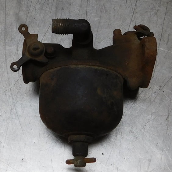
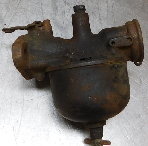
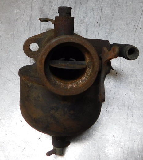
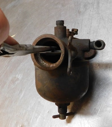
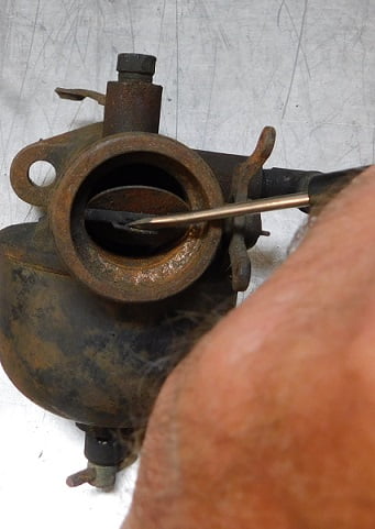
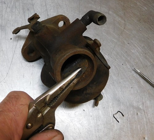
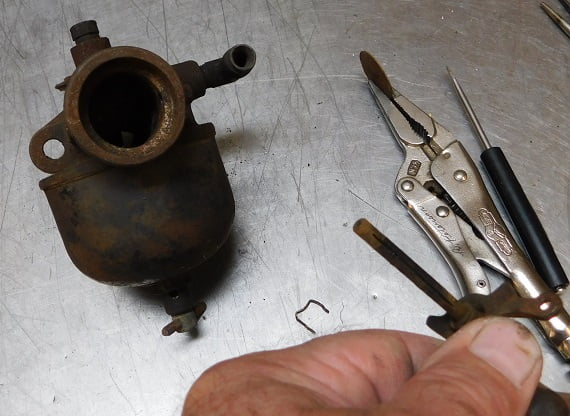
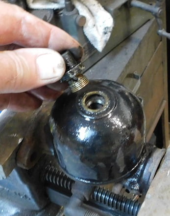
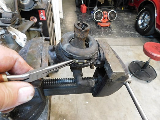
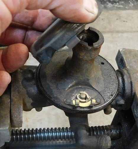
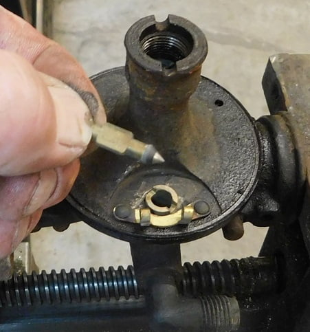
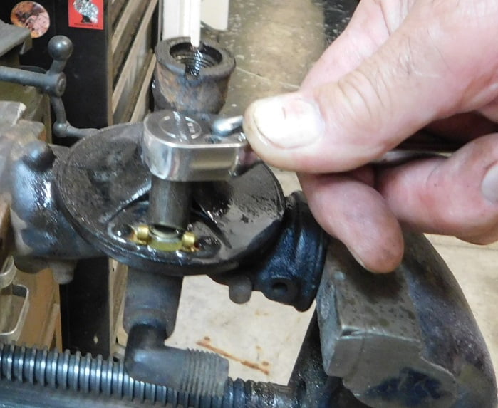
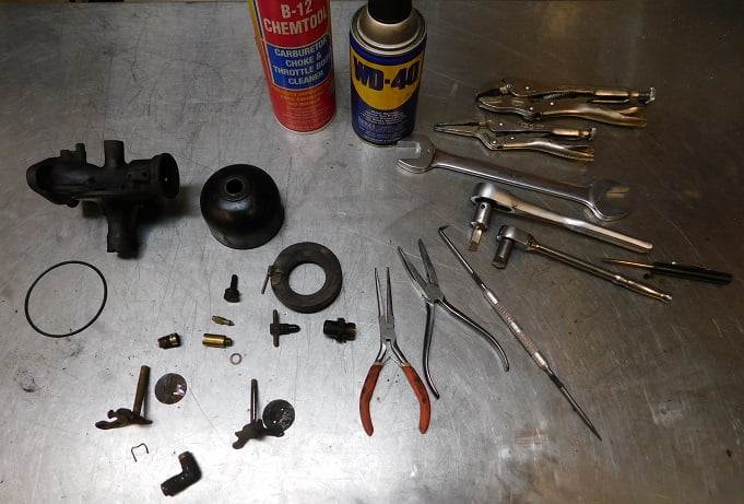
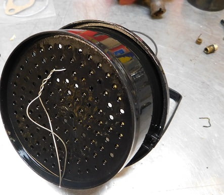
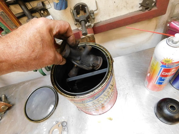
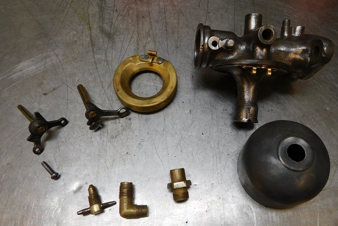
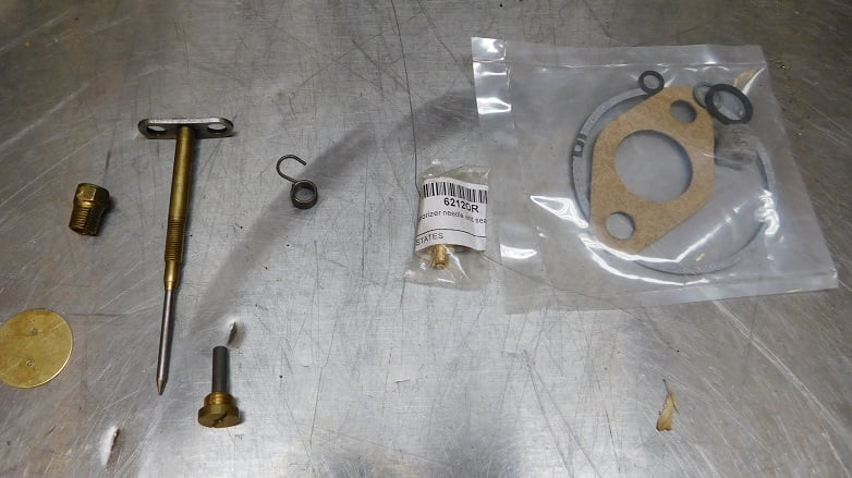
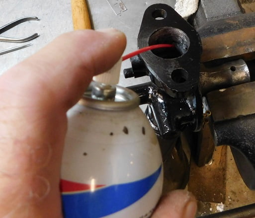
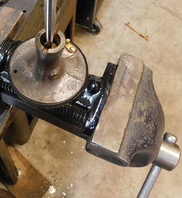
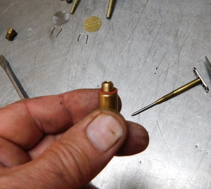
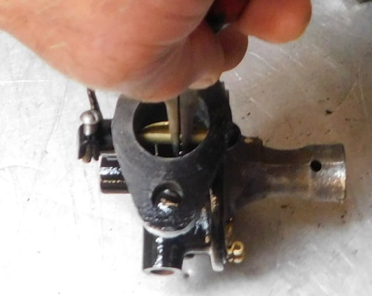
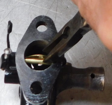
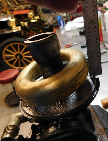
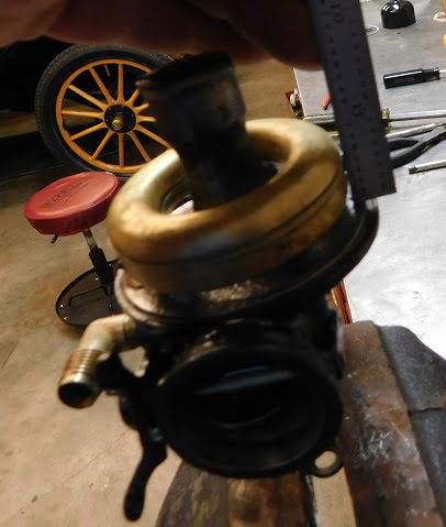
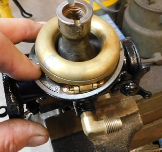
Our subject carburetor is dirty, but not too rusty. The bowl retains much of its original “Raven” finish. Top view of our carburetor shows that the mixture adjusting needle is missing. On the good side, both throttle and choke levers are present and move freely.When selecting a carburetor to buy you want a greasy one, not a rusty one if there is a choice.While the choke lever was present and usable, the choke return spring was broken.Holley published this diagram showing the main parts and how they operate.Another diagram provided by Holley showing the main parts and how they operate in a typical NH carburetor.We start disassembly by straightening the clip securing the choke blade to its shaft.With the legs straightened out the clip can be pried free.Once the clip is high enough you can grab it with pliers and pull it out.Then the blade can be pulled out and the shaft removed.The throttle blade is the later style which does not use a clip; instead they have a bendable tab. To remove it the single inside tab is pushed to be inline with the slot.Then it can be pulled out with a pair of Vice Grip pliers.The throttle shaft then comes right out. This is a really good one with minimal wear.A Holley advertisement from about 1920. We clamp the carburetor in the vice upside down for disassembly of the rest of the parts. Our bowl required penetrating oil on the drain assembly before it finally came loose.It is common for these bowls to be so rusty around the drain that they cannot be re – used. This one is nice and clean with shiny steel below the gasket.Inside the bowl is just what we like – no rust and a misadjusted float that probably caused this carburetor to be removed long ago.We pull the float hinge pin so that the float can be removed.This exposes the fuel inlet needle and seat assembly.The original needle and seat look like new. We are going to replace them, but these are good enough to serve in the future if needed. We will put them in the spares box.The main jet is removed using a specially ground flat blade screwdriver tip and a 3/8″ ratchet after applying some penetrating oil.The inlet seat is removed using a special screwdriver tip in a 1/4″ ratchet.The tension adjuster for the mixture needle is stuck. We had to use Vice Grip pliers to get it out.All the parts that were removed are now ready for their 24 hour stay in the carb cleaner can.The float goes in the basket first……….……….because it is safety wired to the bottom so it cannot float.The rest of the parts are loaded in the basket and the lid goes on the extremely stinky can of nasty chemicals.The parts are left overnight, then scrubbed with Scotch Brite and rinsed in hot water.We bought a few new parts from Chaffins including the gasket set, needle and seat (original Smith brand) choke return spring, main jet and needle, and a throttle blade. Not shown, we laid out and drilled two holes on the original throttle shaft to accept the clip that retains the new throttle blade.The carburetor bowl is installed temporarily using the old gasket and then we spend a little time masking it off for paint.After the paint is dry 24 hours later we arrange the parts in order for final assembly.The Holley NH has two drilled passages that supply fuel to the inlet from the main jet well (arrow). Before assembling the carburetor they need to be checked to be sure they flow unrestricted. The forward passage supplies fuel at idle speeds, the rear one is exposed when the throttle opens.Both passages are checked using Berryman’s carburetor cleaner spray. Occasionally you will find one or both passages blocked by debris. If that happens the next thing to do is to drill out the brass plugs so that the passages can be cleaned with a drill bit. Fortunately ours were clear and we moved on to assembly.We start by dropping the main jet gasket into place.The new main jet is tightened with a normal screwdriver. The slot in the reproduction jet is smaller than the special screwdriver that fits the originals.The gasket is placed on the new fuel inlet seat so that it can be installed.The fuel seat is tightened.The throttle shaft and blade are installed. We made new clips from aircraft grade .041″ stainless steel wire. Needle nose pliers are used to fold the ends inwards.Small duck bill pliers finish the job.The new choke return spring is installed before the shaft is inserted. Then the blade and clip are installed just as the throttle blade was.The fuel inlet fitting is installed finger tight, this is how far I got with fingers alone. We have found that using sealant on these pretty much guarantees a leak and might lubricate the fitting enough so that you will over – tighten the fitting, causing the carburetor body to split.A wrench is used to turn the fitting only enough that it is pointed in the proper direction. Never tighten the fitting more than one turn or you risk splitting the carburetor body, which is the end of that carburetor. Next we install the mixture tension nut finger tight (arrow).The mixture needle is turned in carefully until it just bottoms out. Do not apply any force beyond the point where it just bottoms or you can easily ruin the main jet.The tension nut is then carefully tightened with a wrench just until resistance is felt when turning the mixture adjustment.The fuel inlet needle is dropped in place after we clamp the carb in the vice. Note: look hard at the tip of the needle. If it appears to be ridged or rough you may have to chuck it in a drill and polish it using fine emery cloth.The needle should sit in the seat just about flush, barely protruding where the float touches it..We install the float and secure it with its hinge pin.The float dimension should be 1/4″ at a point 180 degrees from the inlet valve. Ours needs adjustment.Needle nose pliers are used to carefully bend the adjustment arm on our float. We end up removing and reinstalling the float a couple times before we get the setting right.The float measures properly now at 1/4″, and it is parallel with the bowl gasket surface all the way around too.A new bowl gasket is checked for fit.Finally the bowl is set in place, and the drain assembly is installed with a new gasket. Notice that on Holley NH carburetors the gasket goes on the outside of the bowl, which is the opposite of the way the bowl gasket is installed on Kingston L4 carburetors.Our carburetor is done and ready for testing on the car.We actually rebuilt two NH carburetors while we had all the tools out, so both need testing.
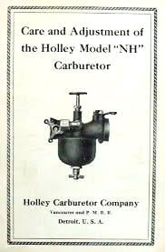
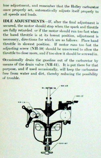
Holley’s instruction sheet is as accurate today as it was when the carburetors were new. We followed the instructions.
Holley NH Instruction booklet, 1920 page 1 – Note that the “strangling shutter” is what we call a choke.Holley NH Instruction booklet, 1920 page 2Holley NH Instruction booklet, 1920 page 3
Epilogue – We finished testing of both Holley NH’s today on the 1910 touring. Both worked very well, with free starts a lot of the time, no leaks, and smooth operation. Once the car warmed up both carburetors seem to work best around 3/4 to about 1 full turn from closed which is certainly in line with the original Holley recommendations.