

Above we see new 1915 Model T Fords coming down the assembly line at the Highland Park plant circa May 1915. The firewall assembly is installed with the steering column still wrapped in its protective brown paper. The horn tube is secured to the steering column with a bit of twine so that it will be out of the way when the body is dropped onto the chassis. Photo property of the Henry Ford museum.
When we left off in our last installment (here’s a link:)
Restoring a Model T Ford Steering Column Part 1 the steering column was disassembled for restoration. In this edition of Model T Ford Fix we finish the job.

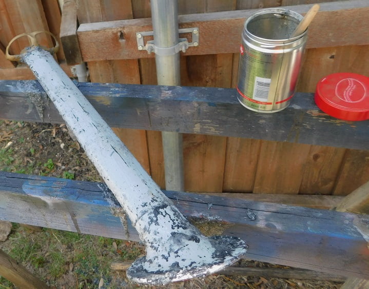
We start by applying paint stripper to the steering column. We use “Aircraft Brand” paint stripper from the home improvement store. A smaller 1 quart metal coffee can is filled part way with stripper, and a small 1″ paint brush is used to spread the stripper on the paint surfaces that need to be removed.
By the second application all of the many coats of cracked black enamel are gone. When the stripper gets down to the spray bondo it stops having any effect. We scrub the column with water and 3M scotchbrite to remove the dried stripper residue. Then we use a pneumatic sander to get the column down to bare metal.
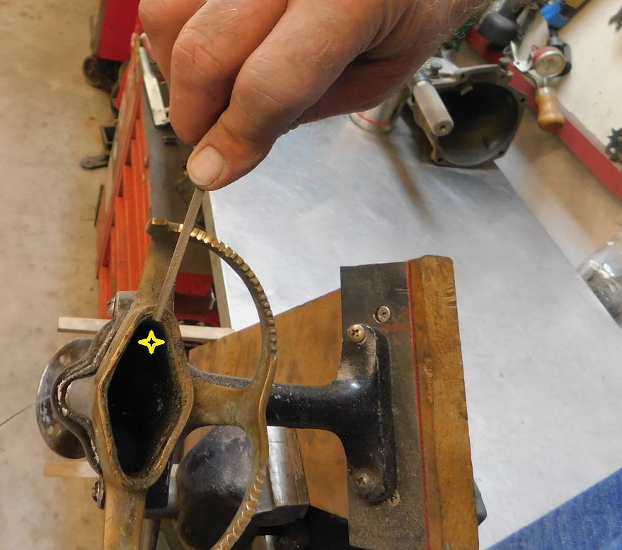
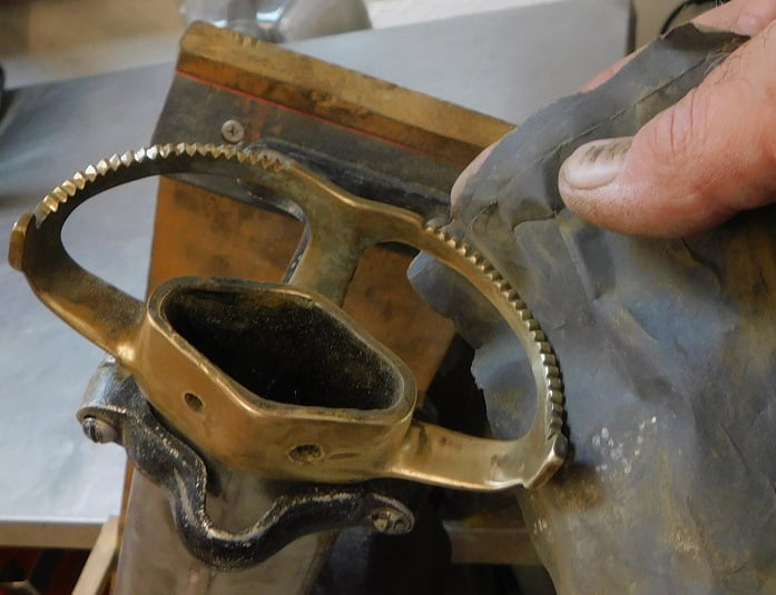
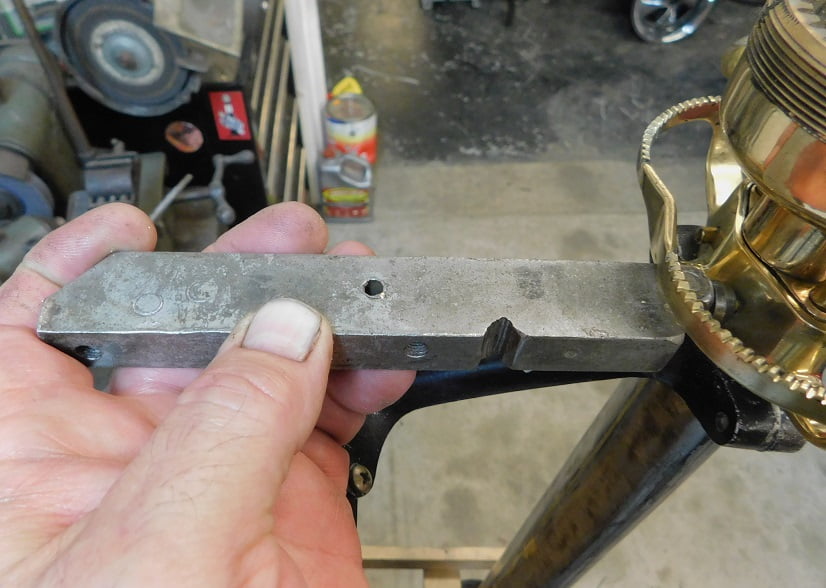
The steering column quadrant was soldered to the column when new. Our steering quadrant is in pretty decent shape except that the teeth have been worn down over the years. We put the entire column in the holding fixture, then clamp the holding fixture in the vice to give us a convenient position for cutting the teeth. A jeweler’s triangular file is used to cut the teeth. Each notch is filed with the file aimed so that it passes over an imaginary center of the control rod, in this case the throttle rod. I put a little yellow star in the center of where the rod would be so that you can picture this concept in the photo above.
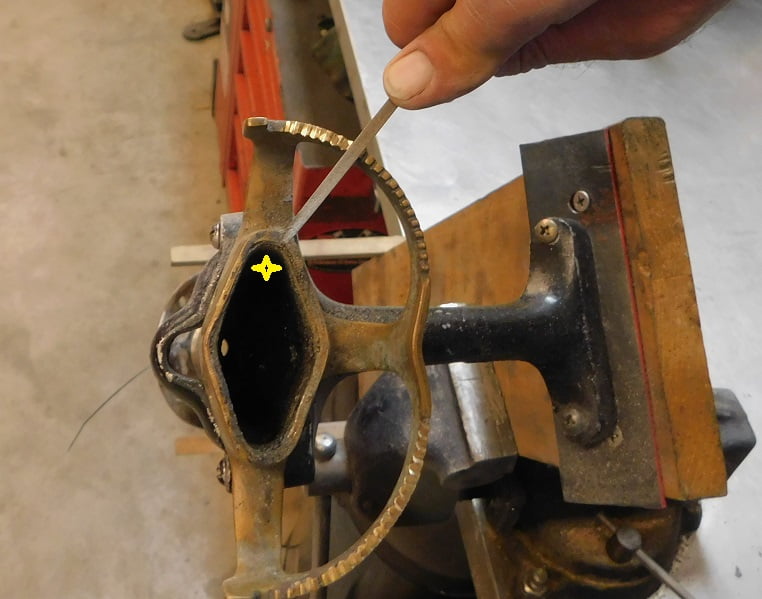
As we progress with the job we continue to keep the file pointed at the imaginary center of the throttle rod.
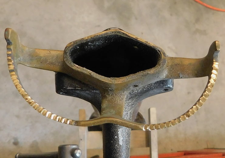
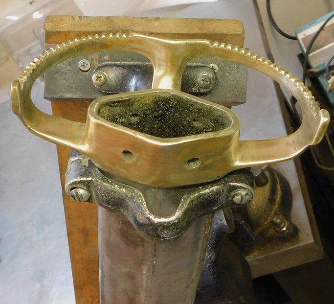
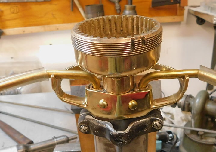
After about thirty minutes of filing we have fresh notches on both the spark and the gas sides of the quadrant.
In preparation for polishing the brass we start sanding all the surfaces with 400 grit wet or dry emery cloth.
The emery cloth makes quick work of the heavy tarnish and removes fine scratches.
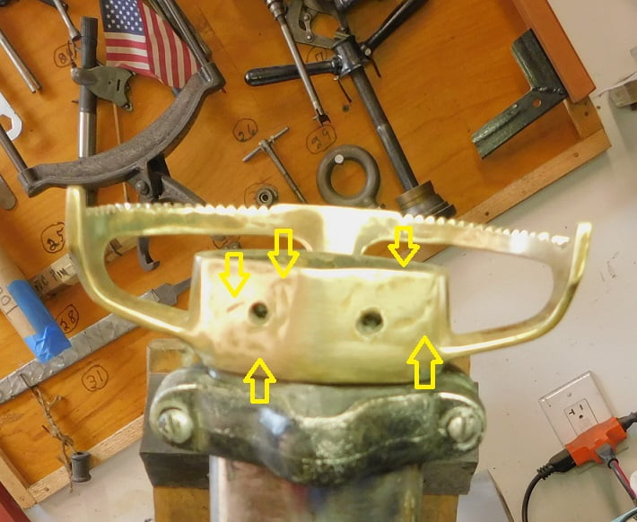
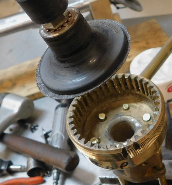
The emery cloth also exposes several dents and dings that were not visible prior to removing all the crusty corrosion. We use a high speed angle grinder with a 1 – 1/2″ diameter 3M scotchbrite wheel to level out the dented areas prior to polishing.
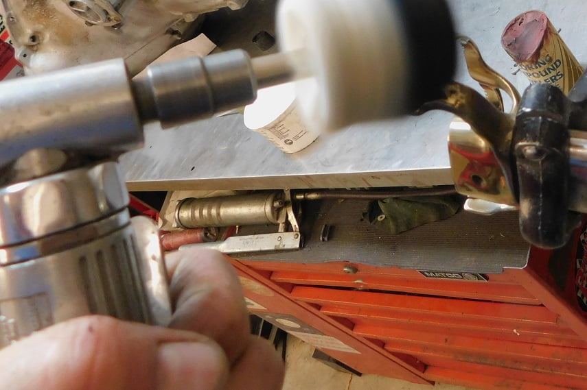
The 90 degree high speed motor is used with a 1 – 1/2″ soft buffer to polish the quadrant. We used red jeweler’s rouge on the cotton buff.

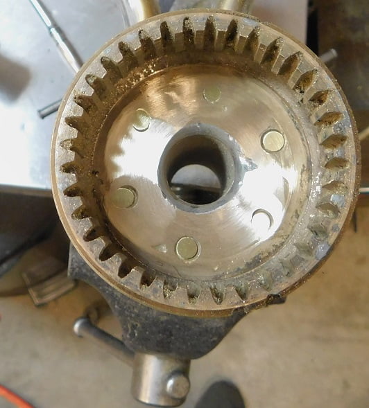
The quadrant is 90 percent polished after using the power buff. Some recessed areas cannot be reached with the wheel so they have to be done by hand.
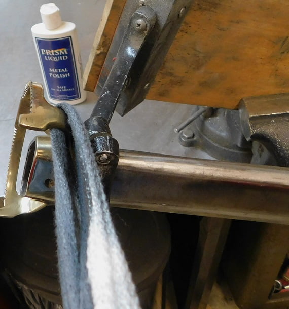
A strip of cheesecloth and some Prism polish finish the job.
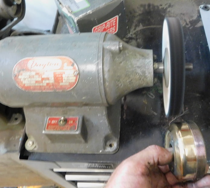
The steering gearbox gets sanded with 400 emery cloth then buffed on the Baldor buffer with a soft cotton 6″ X 1″ wheel using red jeweler’s rouge. Not shown, we had to remove dents from the upper bearing using 100 grit emery cloth, then smoothed out the sanding marks using progressively smoother grades of cloth, followed by buffing on the wheel.
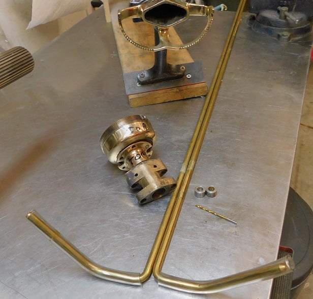
We are using new solid brass rods sourced from Langs Old Car Parts. The rods come with new retaining collars and a drill bit. We compared the length of the new “1909 – 1910″ rods with the old ones. The new rods are about 1/2” longer than the old ones which is fine, we can cut them to length. All the parts are test fit to the column to make sure everything lines up and works prior to riveting. Notice that I have marked the gearbox and the upper bearing “top”. They only align one way. Installing the rods upside down would be a disaster that would result in drilling everything apart and re – riveting. We don’t want to do that!
We install the rods, properly oriented, then use Clecos to secure the upper bearing to the gear box. You could also use small screws and nuts if you don’t have any Clecos.
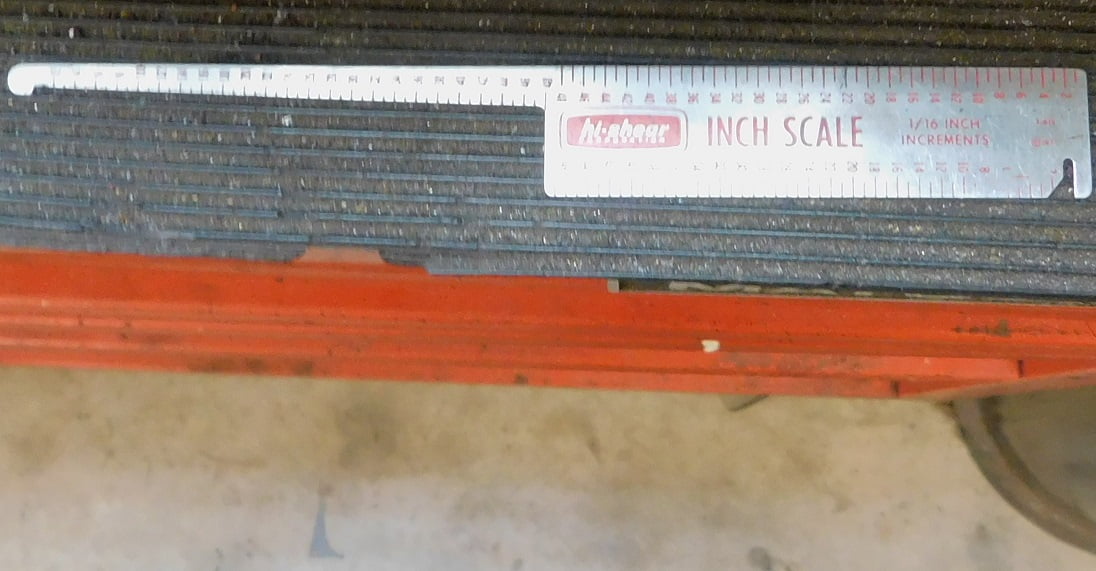
We used the grip gauge above to check the length needed for the rivets. Our column was repaired previously and all the holes in the upper bearing and gear box are now 3/16″ instead of the original 5/32″ diameter.

The grip gauge told us we needed 7/16″ of rivet length prior to bucking. We cut the rivets a bit longer and then looked at them in the hole. Rivets need to be about (1 – 1/2 times the diameter of the rivet) beyond the hole to be proper length. We ended up cutting all the rivets to 7/16″ length.
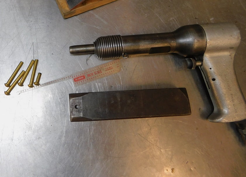
Above we see the 4X ATS brand rivet gun which is a used tool purchased from The Yard Store. Click here for The Yard Store Website
We used a piece of steel 2″ X 3/4″ X 8″ as a bucking bar, it weighs about 2 pounds.
The rivets and the rivet set came from Big Flats Rivet Company. Big Flats Rivet Website
We ground some of the tip off the rivet set to give us better clearance. On a 1 – 10 scale of difficulty, this job rates about a 7. The photo above shows how the bearing is secured in the vise. The rivet gun applies staccato blows to the manufactured head of the rivet. The bucking bar “dances” on the shop head inside the gearbox. With the 4X gun it takes about a two second burst to fully form the rivet.
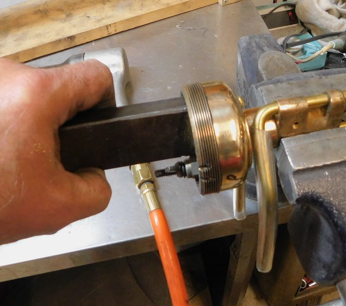
Above we see the position of the bucking bar while shooting the rivet. Combine this photo with the previous one to get an idea of what it looks like to hold the rivet gun n one hand while the bucking bar is in the other hand. It is actually easier to do this by yourself than to have a second person holding one tool or the other. 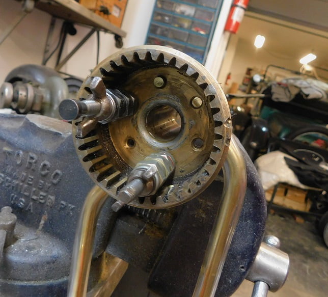
Bucked rivets can be seen in the gearbox above. We remove the Clecos and shoot the rest of the rivets.
We sand the buck tails flush using an 80 grit sanding disc on a 90 degree high speed air motor.
Not shown, we reamed the upper bushing to fit the steering column using an adjustable reamer. Then we cleaned out all the brass chips and powder using Brakleen and a wet – dry vacuum.

The upper bearing and gearbox assembly is installed in the column for the last time. We use a couple of Clecos to secure the parts in place for now.
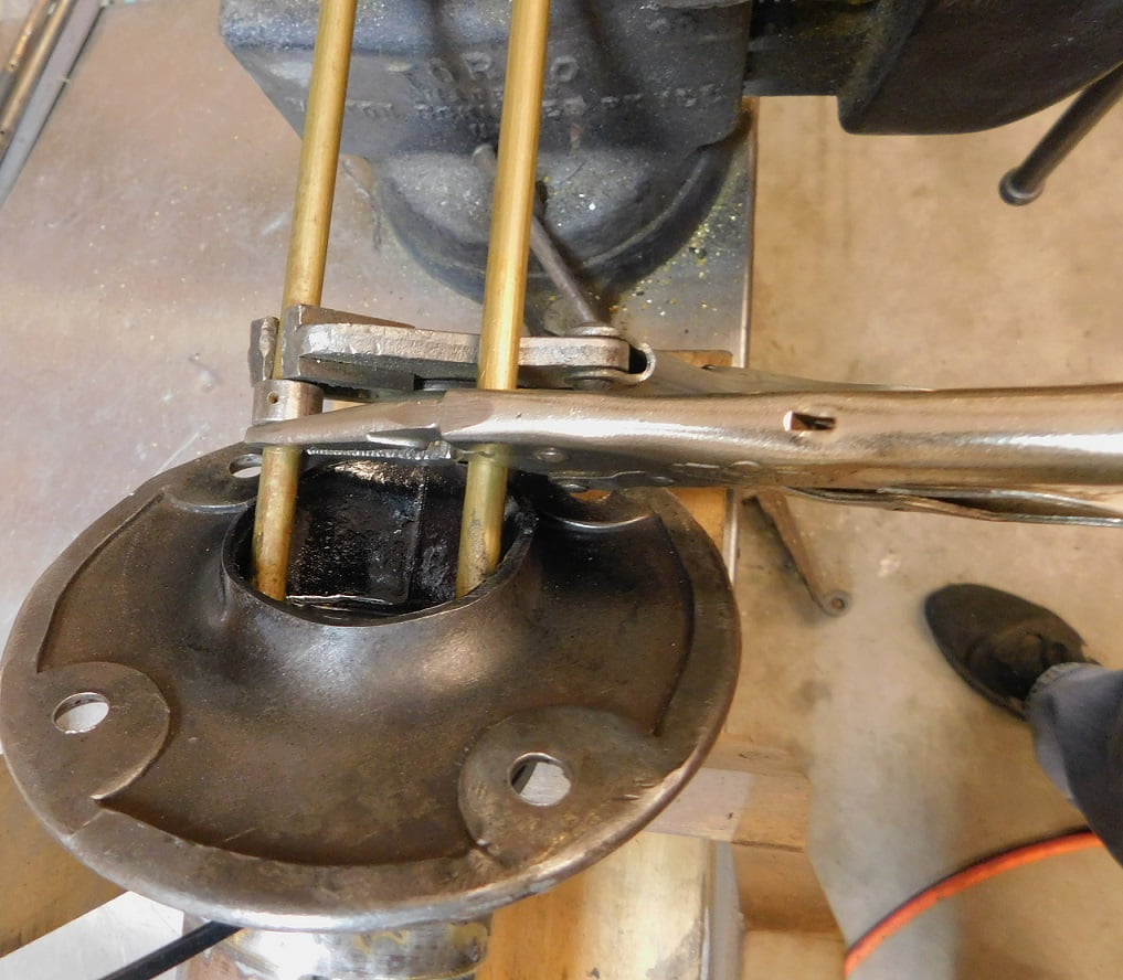
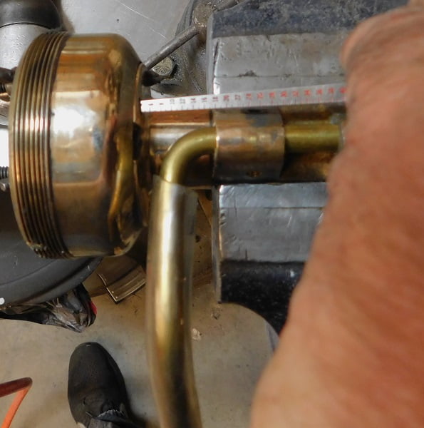
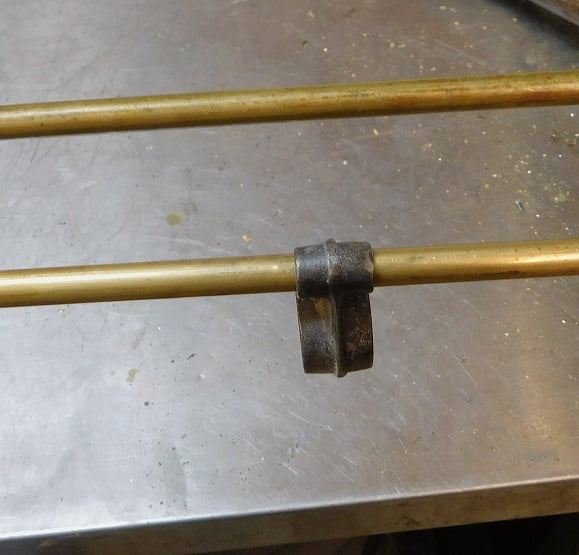
Down at the base of the column we measured the original spark rod to find the correct placement of the spring retaining collars. A couple of vice grip pliers are used to locate the collar at the proper dimension. Measure twice, drill once as they say.
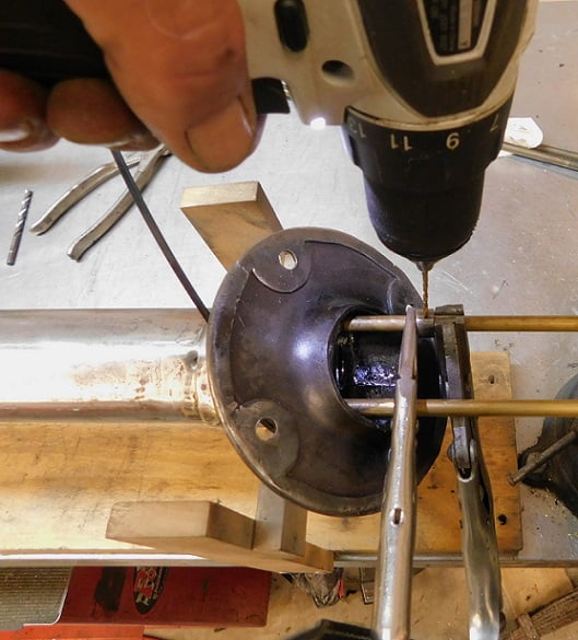
We set the torque very low on the drill to avoid any chance of breaking the drill bit off in the brass.
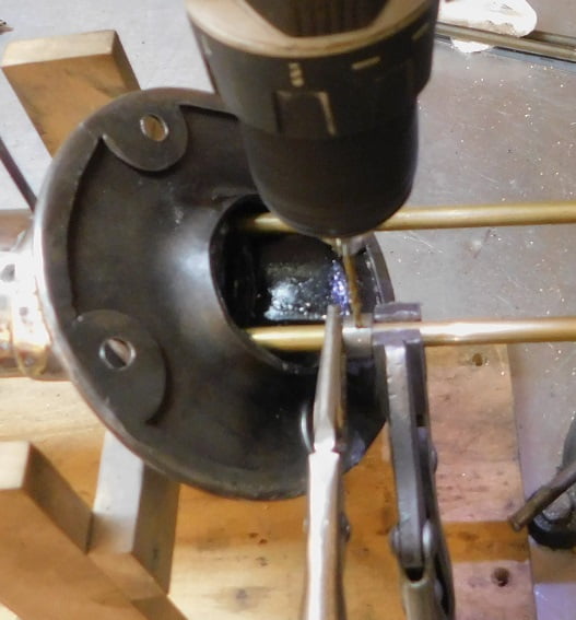
The throttle collar gets drilled.
We install the rivet, aided by a vice grip once again.
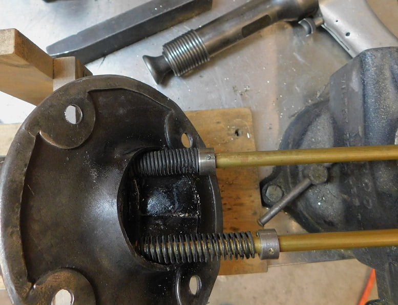
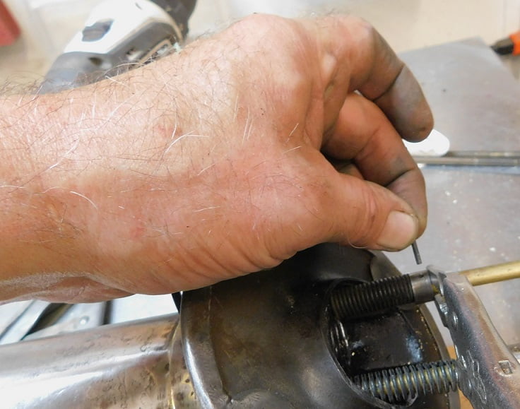
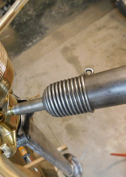
When the rivets are shot they become flush with the outside of the collar. Incidentally, we used the original springs because the reproductions did not look right, not even similar.
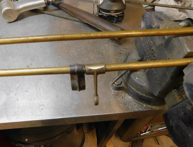
Next we slide the throttle rod guide on the throttle rod before positioning the throttle lever on the rod.
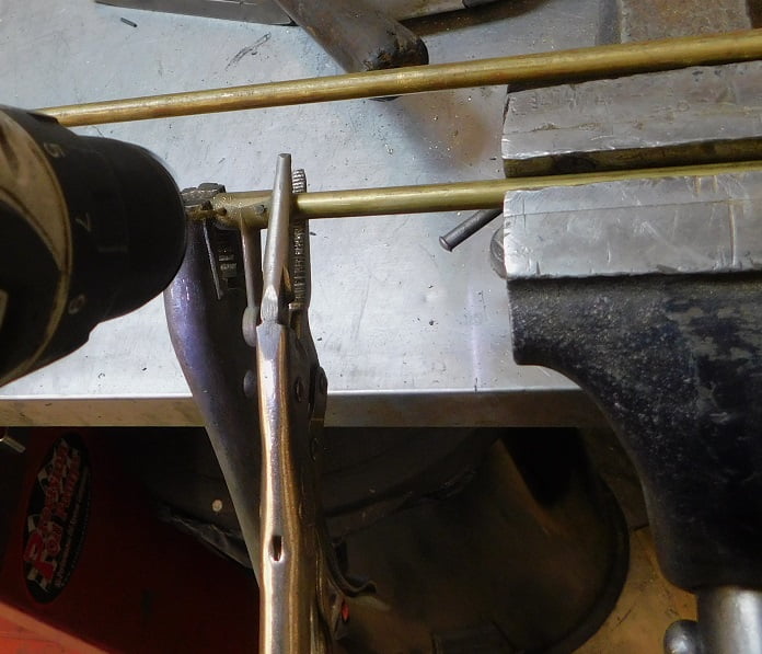
The column support fixture was made the same height as the bench vise for a reason. Here we see the throttle rod clamped in the vise, with a vice grip on each side of the throttle lever while it is drilled. Again we carefully measured the position from the original rod. The throttle lever is drilled with its position at 45 degrees when the lever is all the way up (closed).
The throttle arm is riveted to the rod.
Finally we rivet the upper bearing to the quadrant / tube.
The bucking bar is specially made for this job. It uses a 3/16″ squeeze rivet set installed in a 16 ounce bar made from mild steel. The end of the bar is radiused and cut down to clear everything.
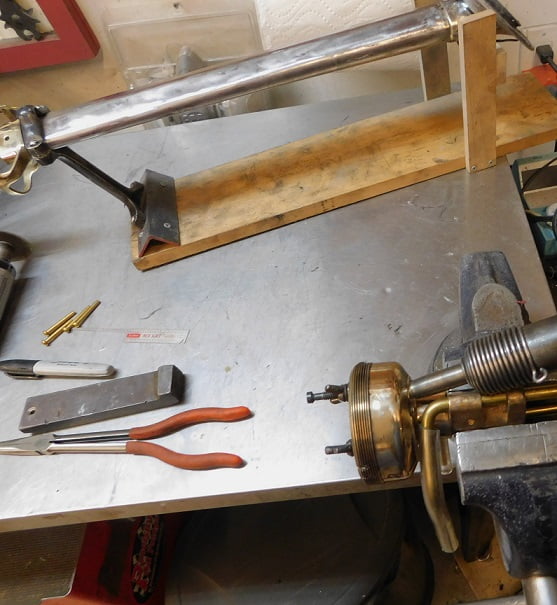
With all the riveting done we can clean up the work bench and put away all the tools. We reassemble the column, making sure to grease both the upper and lower bushing.
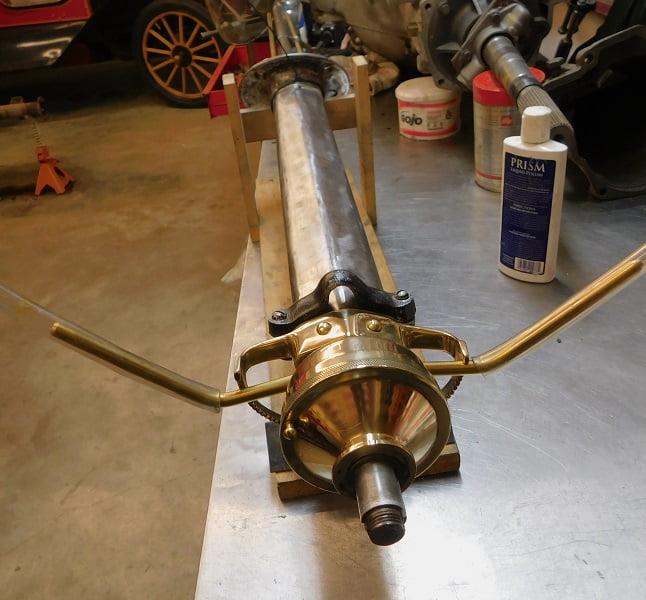
The column is now ready for paint. The spark and throttle levers will get hard rubber knobs on their ends, just like the originals.