
Our 1917 torpedo has developed a bad habit. It likes to shimmy, especially while slowing to a stop for a stop sign. Once it is above 10 MPH, no problem, but every time we slow down it happens, the dreaded death wobble. It begins about 10 MPH, the steering wheel flopping back and forth slowly and gets worse as you slow down. This happened only occasionally until the recent 2017 Texas T Party, where it began to do it nearly every time we slowed down. Not good!

One night at the YO Ranch Hotel a friend helped us inspect the steering components to look for looseness caused by wear. While Tim rocked the steering wheel left to right without moving the front wheels, I was under the car looking to see what moved. The only place that was moving was the bottom of the steering column where it goes through the frame bracket. Apparently the bushings in the steering bracket are completely worn out. We finished the tour carefully, slowing down well before stop signs, and never close to another car.
First let’s look at the evolution of the steering bracket from 1909 – 1927.
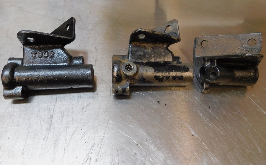
The earliest steering bracket T932 (far left above) was used from 1909 – 1910 and into the beginning of 1911 model year. It is notable for not having a grease fitting. The steering column had to be removed to lube the unit with grease. The fitting had two bushings, top and bottom.
Above (center) T932B (the one still being used in 1917) was introduced some time in mid 1911. It is a slightly different angle than the earlier version, and now a grease fitting is incorporated in the center of the upper bushing. This version was used until the end of 1925 model year. You can distinguish versions made from 1919 – 25 because they have Ford script in the casting marks.
The steering bracket (above right) was further modified and became T932C for the 1926 – 1927 model years. The bracket is much smaller and only one bushing is used. Ford was saving the price of a bushing and used less cast iron, no doubt saving 10 – 20 cents per car.
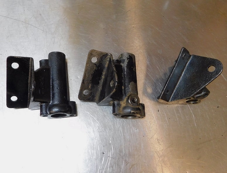
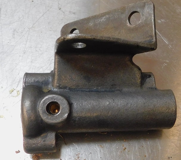
Above, the TT used a bigger, heavier steering bracket that has a different hole pattern than the version used on passenger cars. This one is from 1918 and does not have a casting number or Ford script.
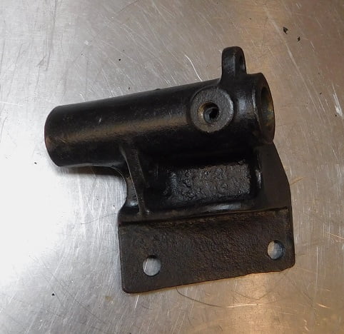
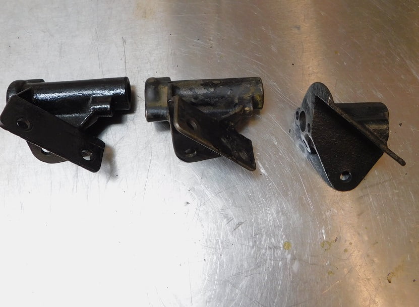
Above, the top view of the beefy TT steering bracket used from 1918 – 1927 model years.

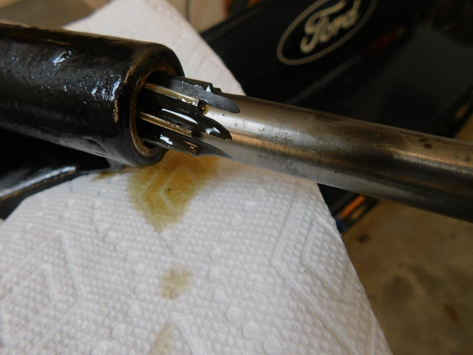
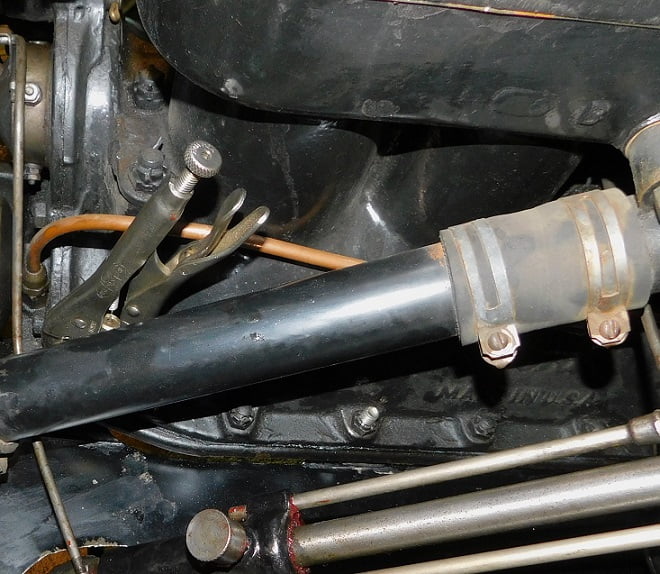
Above, we start removing the worn out bracket by removing the cotter pin and the nut from the spark rod lever. Then we drill out the rivet attaching the lever to the spark rod using a 1/16″ drill bit. Remove the spark lever, and the nut securing the pitman arm to the steering shaft.
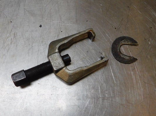
The local offshore tools store has these cheapie tie rod end pullers that work just dandy when removing the steering arm from a Model T steering column. The fit is not quite right, I had to grind out one side of a hardened steel washer to collar the steering arm so it can be pulled off.
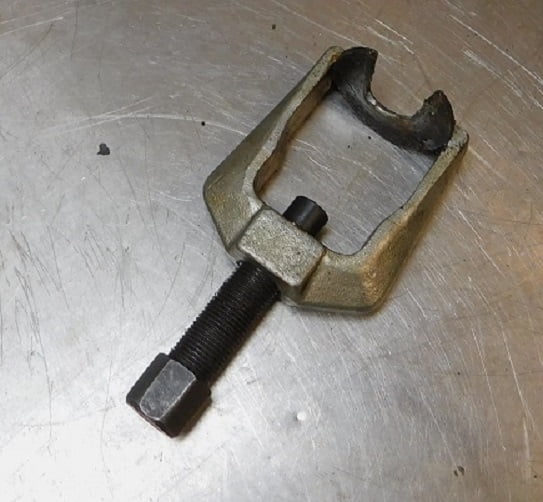
Another view of the puller showing how the washer is fit in between the steering arm and the steering box.
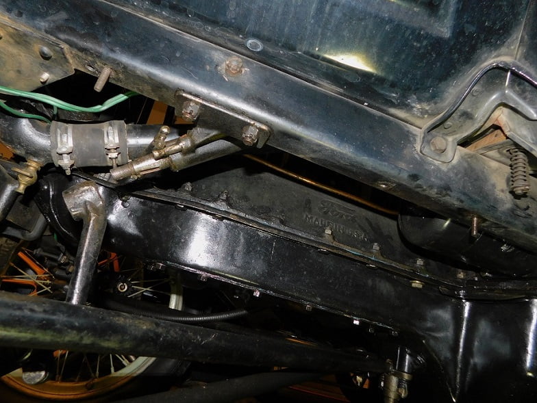
Note – the engine pan had to be removed to clear the pitman arm puller. With the steering pitman arm removed we can remove the cotter pins and the three bolts securing the steering bracket to the frame.
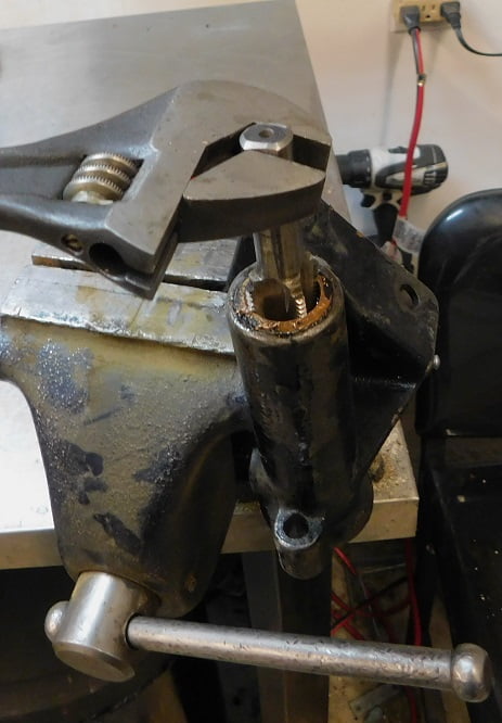
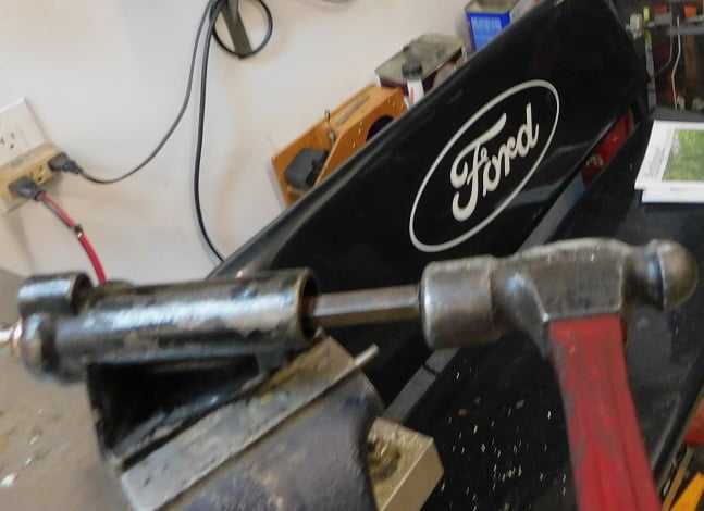
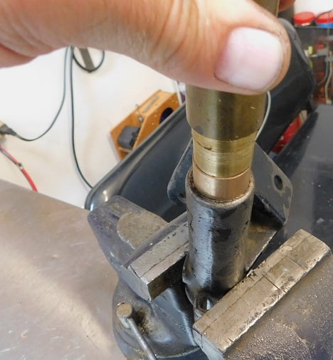
Removing the worn out bushings from the steering bracket is quite easy. First I screw a 7/8″ X 14 NF tap into the bushing above.
With the tap threaded in all the way I turn the bracket over so I can drive out the bushing.
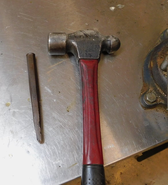
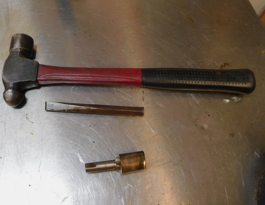
A big hammer and a blunted chisel are used to drive out the bushing.
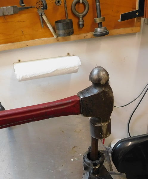
It only takes 4 – 5 good solid blows.
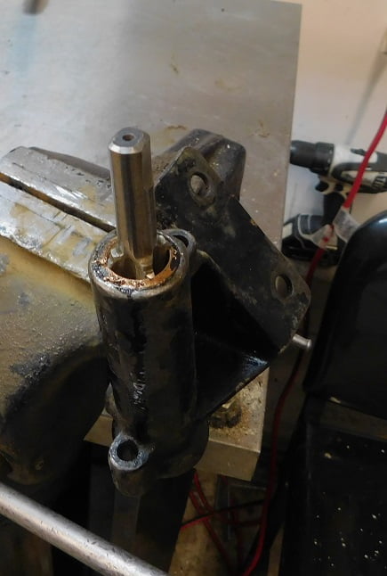
With the bushing out we unscrew the tap from the bushing, and repeat the process for the upper bushing.
Above the upper bushing comes right out. Next is a trip to the parts washer to get rid of all the old grease and brass shavings.
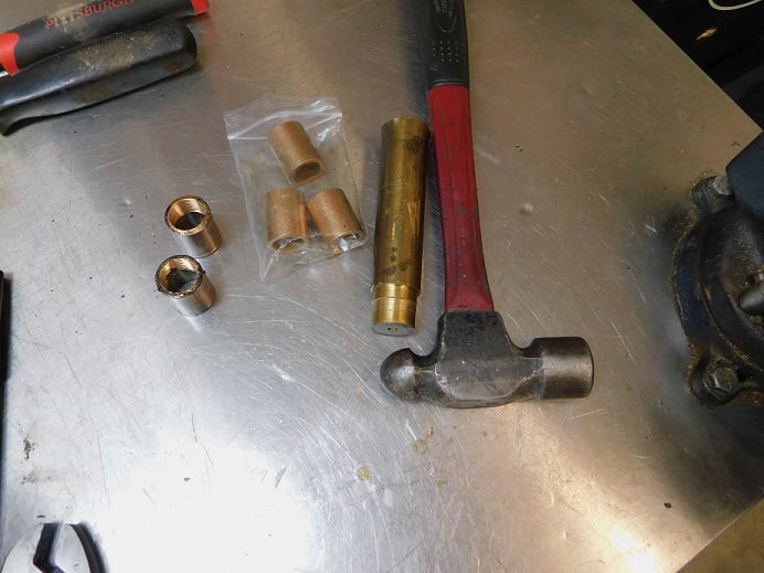
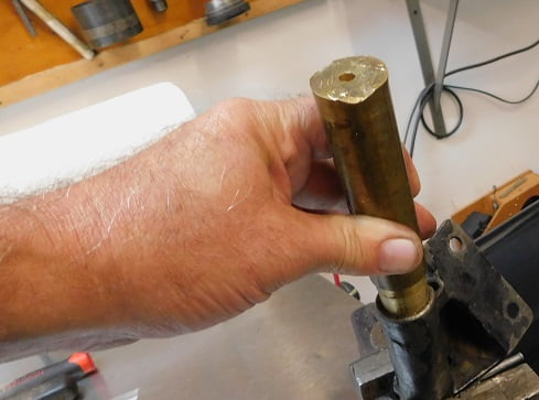
I find a scrap piece of brass and turn down the end on the lathe so that it is .010″ smaller in diameter than the new steering bushings from Lang’s. Any day that we get to use the lathe is a great day!
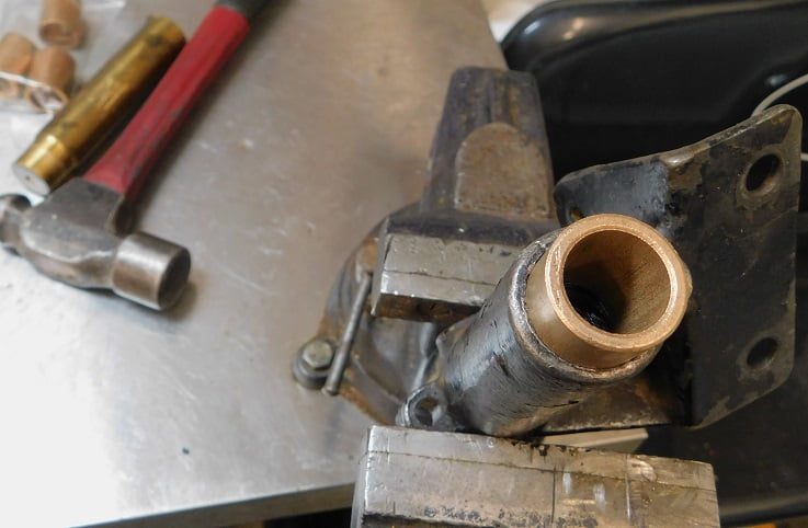
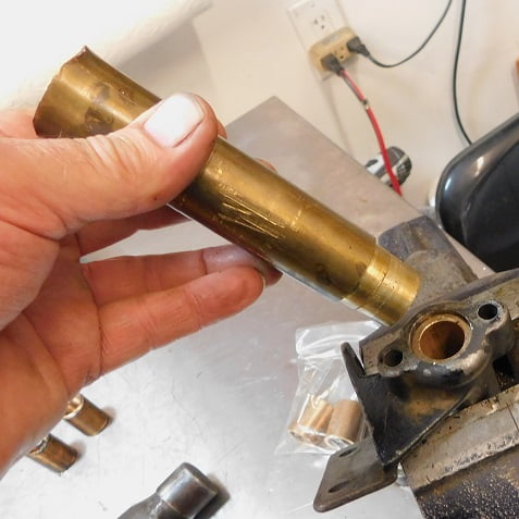
Oil is squirted in the steering bracket and wiped around so it covers the area the bushing fits into. Using the brass driver I hit the driver with the big hammer, stopping every few blows to view the bushing’s progress. You want to push the bushing in until it is just flush – no more.
The bushing is flush with the end. Time to work on the top bushing, this one is done.
Above, we have stopped to take a look at progress on the top bushing. It has to go in far enough to clear the recess for the felt washer / seal. The felt seal keeps water, grease and dirt from getting in to the bushing.
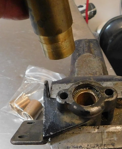
The upper bushing is driven in just enough to clear the recess for the felt washer.
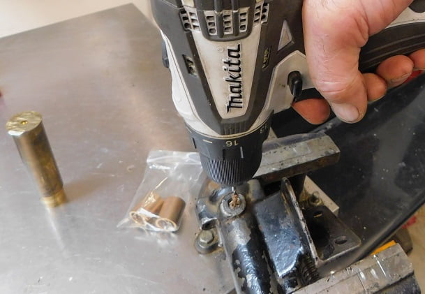
There is no hole in the bushing for grease, so you have to drill it after the bushing is installed in order that it aligns properly. Here (above) we pilot drill 1/8″.
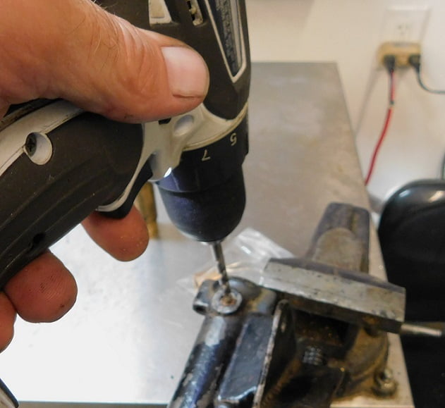
Finish drill 1/4″.
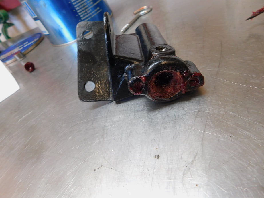
We clean the bracket again in the solvent washer to get rid of the brass shavings. Then use the wire wheel to remove all the old paint.
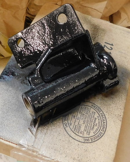
When the paint dries we are almost ready to start assembling things.
We oil up a .750″ reamer after clamping the steering bracket in a vice. The reamer finishes the inside of the bushings, and removes paint over spray.
After reaming we use Brake Kleen spray to remove the brass shavings to avoid damaging the shiny new paint.
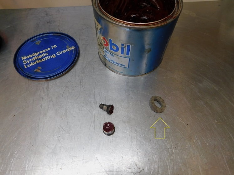
The grease fitting is cleaned and filled with fresh Mobil 28 grease. The new washer is saturated with grease before it is installed in the steering bracket.
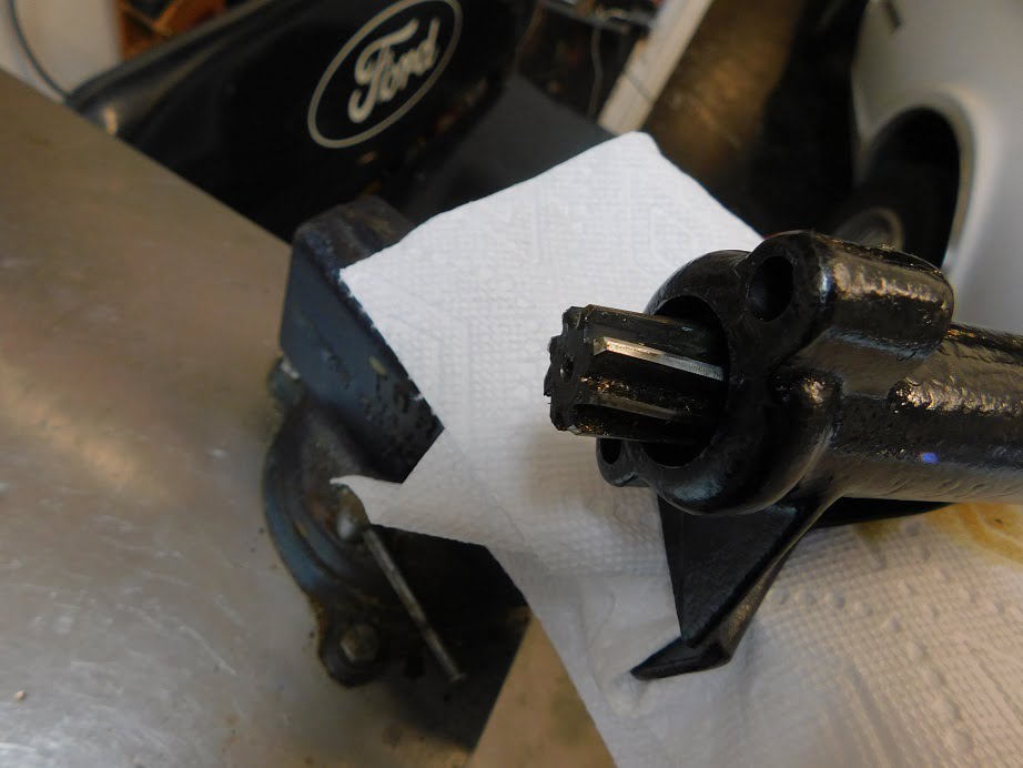
Above the felt washer is stuffed into its groove. I used a screw hook as a tool for this, you could use any blunt object that is about 3/16″ in diameter. Notice also that I have put grease into the throttle and spark rod holes in the steering bracket.
The rest of the job is just reassembling things. One tip that we wanted to share is how to easily tighten the bolts that hold the engine pan to the engine. They are installed with the bolt facing up, just like all the other pan bolts, but left loose so the slotted ears of the engine pan can be installed. We put a vice grip on the nut so that the bolt can be tightened from below without the need for a second person.
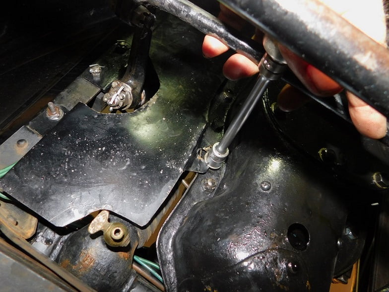
Here we are tightening the last bolt. Not shown, but very important, be sure that all the cotter pins are properly installed in the steering components.
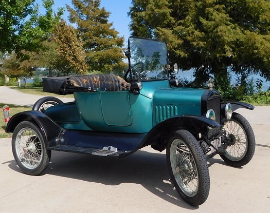
We went for a long drive afterwards. No more shimmy! All is right with the world once again.