

A Model T Ford owner (left) stops at a junk yard during the great depression to buy a few extra coils for his Model T. The junk yard owner is evaluating the coils.
The heart and soul of the Model T Ford is its ignition system. Very advanced for its day, it is widely misunderstood by many in the car hobby. Many do not comprehend how utterly reliable and trouble free the Model T ignition system is when it is properly serviced. Here we will examine the flywheel magnets and care for them properly during an engine service event.
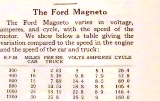
The main component of a Model T magneto is what we would today call a variable frequency variable voltage permanent magnet alternator. The chart above was published by Ford to show what the typical magneto output should be in a Model T Ford. The output will be lower if the magnets are not fully charged. While the engine is apart the magnets can be charged.

Above we have bolted the flywheel to a workbench holding fixture to speed the job. A large slot head screwdriver is used to break loose the screws retaining the outer end of the magnets. A hammer is used to tap the screwdriver to make sure it is seated properly. The screwdriver has a square shank allowing easy turning of the peened over screws. Sometimes it is necessary to grind off the peened over ends of the brass screws first. In any case, the screws are thrown away and replaced by new ones.
Warning: Original Ford magneto screws and flywheels (or ring gears on later T’s) are tapped for #14-24 screws. Reproduction magneto screws are 1/4 – 24 thread, which is close but not the same. New screws in either thread are available from the T part sellers.

Safety wire is cut on the center row of bolts securing the inside of each magnet. I break them loose with a ratchet. Then they can be removed with a speed handle. The magnets are kept in order as they are removed, with the upper side staying upward. We take a moment with each magnet to inspect for cracks, then whack each magnet soundly against the vice to see if it is weak enough to break in half. You want any marginal magnets to fail now, not in the engine at driving speed!
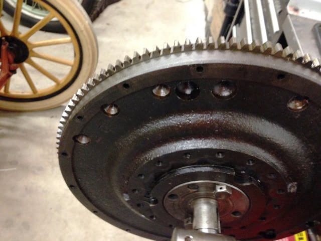
Our flywheel is from a 1919 or later engine. It is being used with a 1915 engine. The ring gear looks absolutely perfect. It has been started for the past 30 years using a 12 volt battery and an unmodified T starter. It will last another 100 years we think. If the flywheel were from a 1918 or earlier Model T the screws thread into the flywheel itself, there is no ring gear and no provision for a starter on the earlier cars.
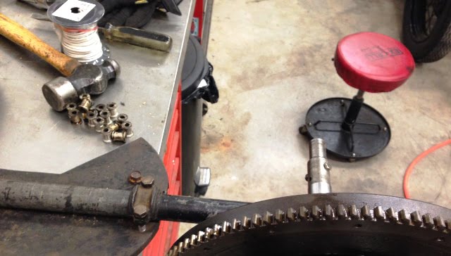
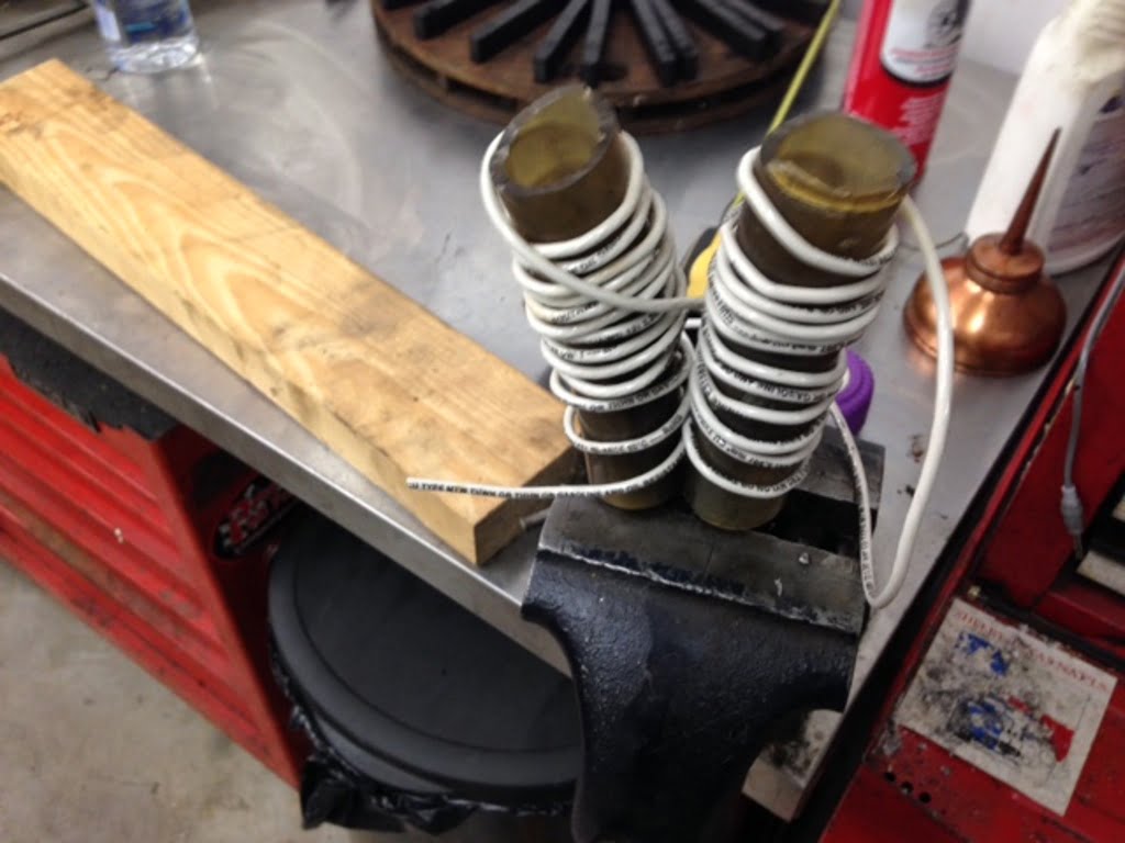
A magnet charger is made using one of our magnets clamped in the vice. I put a piece of 1 1/4″ ID Tygon tubing over each end of the magnet. Then I wrap 12 turns of # 10 AWG stranded wire around the Tygon tubing starting at the top of one magnet end, reversing the wire turns at the center of the magnet and continuing up the other side of the magnet with the same number of turns wound in the opposite direction. Some black duct tape is applied to the wire to secure it in place. Our low buck magnet charger is ready for action!
I wrap the wire with duct tape to secure it to the plastic tubing. Then I crimp a terminal end on each of the wires, and screw the terminal ends to a piece of scrap 2 X 4 board. The screws are 1/4″ brass screws with a spacer between the screw and the terminal. This allows a jumper cable to be attached to one of the screws. I connect both ends of the jumper cables to a fully charged 12 volt battery. You can use a pair of six volt batteries, or a whole lot of batteries in series to make even more voltage if you like. I’ve heard of folks using 24, 36, even 48 volts. My experience has been that 12 volts is plenty. With the magnet right side up strike the jumper cable on the + terminal several times. I do it three times, some folks do it 10 times. Again, what I do works for me.
CAUTION: Do not clamp both the jumper cables to the screws, you can cause the battery to be damaged or even explode. Perform this operation in a well ventilated area, battery fumes can be explosive.
I spray the end towards the positive cable with yellow paint and then place the charged magnet on a round board to keep the magnets in order. The next magnet is flipped upside down, charged, sprayed yellow, and then flipped right side up before placing it on the round board next to its opposite charged brother. The magnets have to be installed with like charged terminals next to one another in order to function. The arrow points at the charged magnets showing the painted ends adjacent to one another.
The recharged magnets can be tested (if desired). A good magnet will pick up 4 pounds or more. I have a big old 12″ Crescent wrench that I can pick up with the freshly charged magnet, it weighs in excess of 4 pounds. We are good to go back together!
The recharged magnets are reinstalled on the flywheel using a new set of screws. For the time being we don’t peen over the screw ends.
A magnet height checking tool is used to determine the highest and lowest magnet keeper. The magnets need to be the same height relative to the transmission shaft. We find a few magnets that are “out” – too high – by as much as .02″ so some adjustment is needed.
We use a brass hammer to tap on the “too high” keepers, then tighten those screws. Eventually all the keepers are the same height, we re – check the screws for tightness, and then peen over the ends of the screws. Note – do not tap the keepers with a steel hammer, this can decrease magnetism. Some folks like to shim the magnet spools or grind off the spools to adjust the height. Again, I do what works for me and if you think you have a better method by all means do that if it makes you happier. The main thing to remember is that the magnets all need to be the same height in order that the magnet gap can be adjusted properly when the flywheel is installed.