
The weakest part of the Model T Ford design is the rear axle. OK, sure, it was well designed for its time, and perfectly adequate when the car was new. The fact is, if any part of it fails, the car won’t go forward, and it won’t stop either. People have been killed or injured because their rear axle failed in a Model T.

This article is about the drive shaft assembly. We are going to rebuild it as a Ford mechanic would have done back in the day. First let’s take it apart and see what we have to work with.
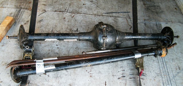
This drive shaft came to us as part of a purchase made at a swap meet. This was a complete small drum Ruckstell axle, supposedly in good shape, needing “just a bit of work on the shift lock”. As things turned out the unit was worth what I paid but needed a complete overhaul.
Please note that there are many good books, videos, and websites available to help you understand what is needed here. I recommend that at a very minimum you should own a copy of the Model T Ford factory shop manual. The information is invaluable, and there are many things in it that are not discussed here.
First we need to disassemble the drive shaft. The first step is to remove the drive shaft pin.

There are two access covers above and below the pin that must be removed first. Then the pin can be punched out using a 1/4″ pin punch and a good sized hammer. Toss the pin, it can only be used once. Sometimes you have to drill the pin to get it free, in that case drill using a 1/4″ bit on one side only. Drill it about 1/4″ in, then punch it out.
Then the u – joint can be pulled out.
With the u-joint removed the drive shaft can be removed from its housing. Before removing it we wiggle the drive shaft in the front bushing to see if there is noticeable movement. Uh – Oh. There is all kinds of movement. The drive shaft bushing is shot. Subsequently I found that the bushing was “wallered out” probably from lack of lubrication for many decades. It measured about .100″ oversize on the inside diameter – completely destroyed.
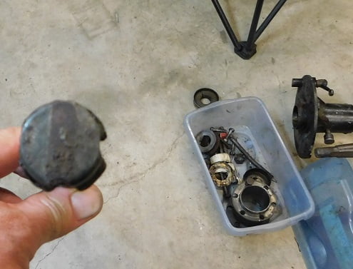
Removing the drive shaft bushing from the tube is easy. First pull out the driveshaft and set it to one side. A tool can be made from galvanized water pipe and a pipe cap very inexpensively. The pipe cap will need to be altered slightly to clear the rivets inside the Model T drive shaft tube. As you can see in the photo below it is ground every 90 degrees so it can pass by the rivets:
The tool is made from 1/2″ galvanized pipe, a piece that is 60 inches (5 feet) long. 1/2″ water pipe measures .840″ on its outside diameter, the size designation refers to the inside diameter. The cap measures a little less than 1 inch outside diameter at its smallest dimension – perfect for our tool.
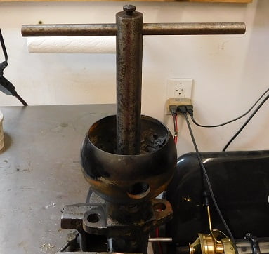
To use the tool, we first turn the driveshaft tube so that the ball end is on the floor. Drop the tool in the end with the cap first. Carefully determine by feel the point where the cap clears the rivets. Then you can hit the end to seat the cap in the bushing.
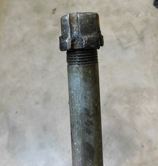
The entire drive shaft tube with the tool still inside is rotated with the ball end up. Then slam the pipe against the garage floor. The inertia of the weight from the drive shaft tube will push the bushing upwards and out. Here is our sad looking bushing after removal:
The original Model T drive shaft bushings are made from Babbitt. This provides an excellent and trouble free bearing if it is lubricated on a regular basis. Another good feature of Babbitt bushings is that if someone neglects to lubricate the bushing it wears out but the steel drive shaft is not damaged. This was true in our case, the drive shaft measures .995″ where it passes through the bushing, virtually like new and not scored.
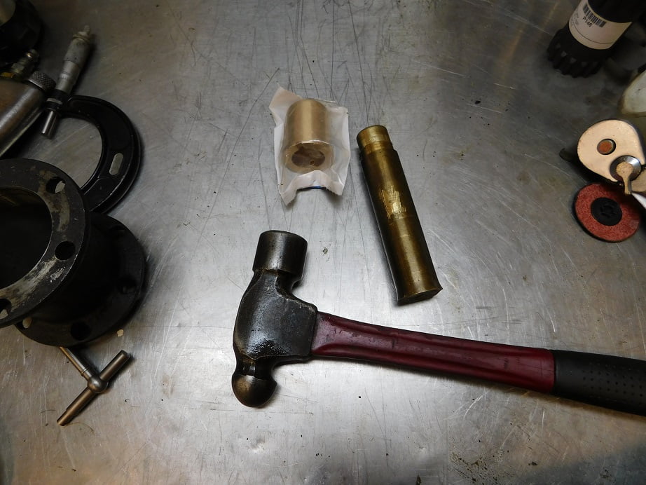
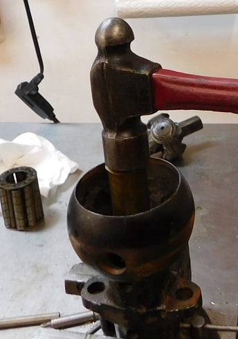
The drive shaft tube is cleaned inside using Varsol and a series of rags pushed through with the bushing removal tool. A new bushing is driven in with a home made driver – I used a scrap of brass turned on the lathe:
The bushing is lubed and driven home. Note that the face of the bushing is the thrust surface that retains the drive shaft. This locates the pinion gear in relation to the ring gear. It is often necessary to face off the drive shaft bushing in order to get the distance set properly in order to align the hole so that the U – joint rivet can be installed. With this in mind I faced off the bushing .010″ on the lathe prior to installation because from past experience they always need to be dressed this much.
With the drive shaft tube done we next look at the drive shaft itself. The cotter pin is removed from the nut and the nut removed so that the gear can be pulled off. Our nut was only finger tight once the pin was pulled!
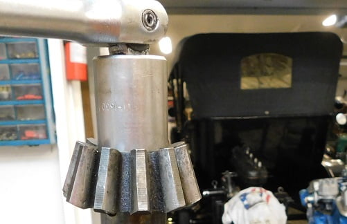
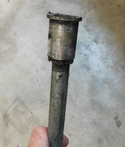
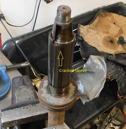
With the gear removed we can lift off the pinion bearing and look at the bearing sleeve. Not sure if it shows well in this photo, but there is a crack about 1/2″ long leading downward from the notch in the sleeve:
We set up the drive shaft for sleeve removal with the square end firmly clamped in the vise:
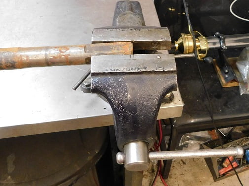
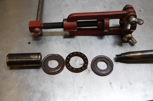
The Stevens drive shaft bushing remover is installed:
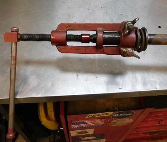
The handle takes both hands to turn. The Acme threads on the tool are oiled to make this easier.
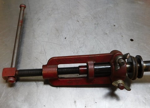
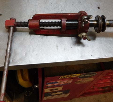
Eventually the sleeve is off and we can inspect the drive shaft thrust bearing assembly. It appears to have been underwater at some point and is rusty junk. All of these parts need to be replaced.
If this was run in the car for any length of time it would disintegrate. The bearing parts would then become cutting blades. Eventually they slice right through the drive shaft until the drive shaft snaps. Then the occupants of the car are at great risk of injury or death.
The drive shaft is inspected with a bright light and magnifying glass. There is no sign of scoring, cracks or gouges. We have found the second good part in the assembly, everything was bad except the tube and the shaft.
A new old stock Ford thrust bearing assembly is dropped on the drive shaft. A new sleeve purchased from Chaffins is greased inside and driven on the shaft using the old sleeve and a large hammer. The notch in the new sleeve is aligned carefully before driving the sleeve, it needs to be properly located to clear the keyway. A new half moon key is installed.

The gear is test fit to make sure it completely seats on the shaft without contacting the sleeve. The sleeve is driven on the shaft just far enough to clear the bottom of the pinion gear.
We install the new pinion gear and mark the position of the cotter pin on the shaft with a Sharpie.
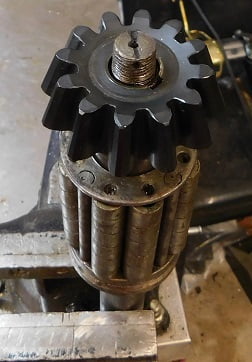
With the square end of the drive shaft clamped in the vise we tighten the pinion nut with a 20″ breaker bar until it is very tight. We inspect the castle nut and then continue tightening until the next slot aligns.

A new stainless steel cotter pin is installed.

The drive shaft spool is inspected for wear. It shows no wear, and there are no cuts, scoring or gouges. We clean it in the parts washer and install new gaskets on both ends with contact cement. The new thrust bearing and pinion bearing are packed with Mobil #28 grease.
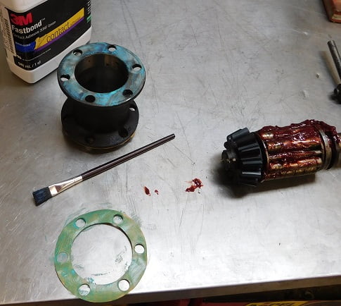
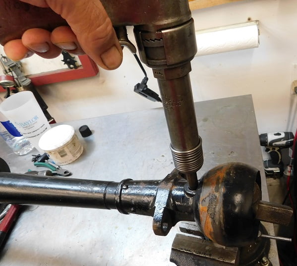
We use a couple of the drive shaft pinion bolts and nuts to secure the spool to the drive shaft tube. We assemble the shaft in the tube to check if the U – Joint pin can be easily inserted. The thickness of the gaskets has moved the parts enough that the pin cannot be inserted. We need to face off the drive shaft bushing a bit more using the Stevens drive shaft bushing cutter.
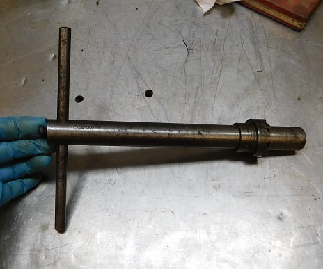
It has a 1″ pilot with a 1 1/2″ spot face. It is used by hand for a few turns until the pin can be inserted easily.
Once we are happy with the pin alignment we drill a 1/4″ hole in the drive shaft bushing for the grease cup. If you don’t drill the hole there will be no way to grease the bushing! The drive shaft tube is then cleaned for the last time, we rinsed it out with soapy water, then the garden hose, then alcohol, then compressed air.
The end of the drive shaft is supported. I used some old empty metal gallon cans. One is dented in the middle to get the drive shaft cradled so I can’t roll away.

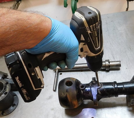
A pin punch is clamped in the vice so that the big end is up. The big end rests against the U – joint inside the hole in the drive shaft tube. A rivet gun is used to swell the pin, the drive shaft is flipped over several times as the pin swells on each end until it is equally smashed and the drive shaft can be rotated with no contact of the pin against the housing.
Let’s review. Our drive shaft had the following bad parts that had to be replaced:
U Joint
U Joint Pin
Drive shaft bushing
Drive shaft pinion sleeve
Pinion thrust bearing assembly
Pinion gear key
Spool gaskets
Total time to do the job was about 4 hours.