
The Holley Model G carburetor was used on millions of Model T Fords starting with the 1914 model year, around July 1913. The Holley G is a very simple, reliable carburetor. Ford used versions of this carburetor from 1914 model year until some time in 1920 with Holley as its primary supplier of carburetors, Kingston being a secondary supplier during those years.
We got this particular Holley G from a friend in a swap involving some unneeded parts, so let’s say that our investment here is quite low. This is the earliest type of Holley G and would have been used in 1914. It has a brass body, brass float bowl, cork float, and a lock screw on the throttle idle stop adjuster. Let’s take a look at what needs to be done to turn this tired old corroded carburetor into a more presentable, rebuilt carburetor.
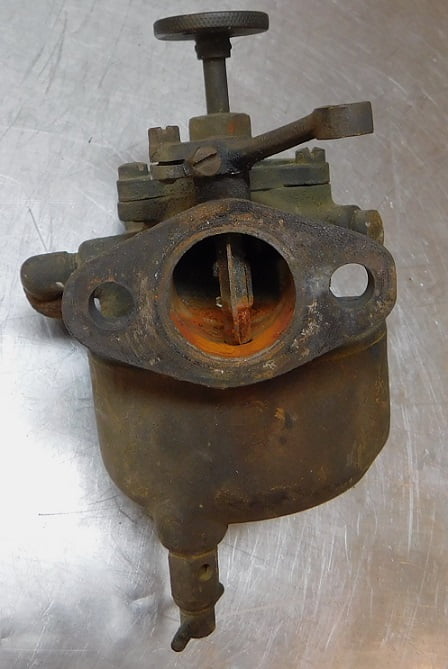
A few more “before” photos show evidence this carburetor may have been submerged in water at some point in its post – operational history.
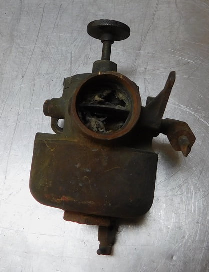
The choke arm on Holley Model G carburetors made before 1919 model year has no provision for a choke inside the car.

This can only get better. Let’s start taking it apart.

We start by spraying all the fasteners with penetrating oil.

With the carburetor clamped in the vice we use a 1 1/2″ socket and a 24″ breaker bar to try to loosen the bowl nut. It resists us, and cannot be loosened.

We tried heating the nut. letting everything cool, applying more penetrating oil. Then we repeated the process. Then we repeated the process. Then we repeated the process. Then we repeated the process. It never worked.

We took a different approach. We drilled about 1/2 way through the nut on two sides 180 degrees apart. Then we applied a chisel blow to the center of each partially drilled hole. The chisel action causes the nut to expand, loosening its grip on the threads.

The nut comes right off.
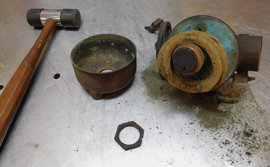
With the nut off a rubber mallet is used to gently tap around the edge of the bowl where it meets the carburetor body. With the bowl off we can see that the cork float is done, but fortunately all the other parts are present and in good shape.

The idle fuel pickup tube is in place and in nice condition. We give it a squirt of penetrating oil and it comes right off.
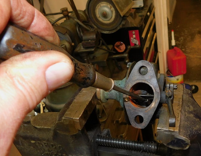
The steel staples holding the throttle and choke blades in place are carefully bent straight and removed. Then the throttle and choke plates can be carefully pulled out using duck billed pliers.

About half the parts can fit in the basket of our Berryman’s Chem Dip carburetor cleaning tank at a time. Each of the two batches is allowed to soak 24 hours.

The next day we pull the parts out.

We rinse the parts off with warm water and blow them dry with an air blower. Note the tar all over the carburetor body near where it attaches to the intake. We think this car had a oil leak for years and that the crud built up and solidified. A small screwdriver was used to pry off the tar.

Next we placed all the parts in our Lyman ultrasonic parts cleaner. We mixed a batch of fresh solution, about 84 ounces was needed to cover the carburetor.

We set the cleaner to 10 minutes and let it do its job. Then we repeated the process several times for a total of 1 hour.

Next all the parts went in the Lyman vibratory cleaner and we covered them with corn cob media. This runs for an hour while we go to lunch. After lunch we take out the parts, blow them all out with compressed air to remove any media, and reject any parts with issues. Our bowl nut was already bad, and the brass bowl turned out to have serious cracks. Both parts needed to be replaced.

We looked through several boxes of spare carburetor parts until we found a good bowl nut. We don’t have any good brass float bowls, so a later steel float bowl was robbed from the spare float bowl collection.

Above, the crusty old bowl nut would not have looked good even if we had not drilled and chiseled it on two sides. It went in the trash.

We picked the pieces of broken choke spring out of the choke lever with a hook scribe.

A piece of 1/16″ spring steel is wrapped around a suitable sized screwdriver clamped in the vice to make a new choke spring.

Above, we test fit the new spring. It works.

The yellow arrow points to extreme wear on the throttle shaft. We take the throttle assembly to the belt sander and grind the worn area to make it fairly uniform in diameter.

This cigar box full of various sizes of brass, steel, copper and aluminum tubing has been quite handy over the years. We find a piece of thick walled 1/4″ diameter brass tubing to make a repair bushing for the shaft.

We cut off a piece of the tubing about 1/2″ long using an Imperial Eastman tube cutter.

We put flux where we want solder to go, then (not shown) make sure everything is aligned before soldering.

With the new piece soldered in place the throttle is going to fit much better.

We grind the repair to length, and bevel the end.

The throttle shaft after repair. Note the hex headed throttle screw and throttle lock screws, typical of 1914.

We need to make some new staples to replace the old rusty steel ones that were originally used. We select a box of stainless steel safety wire. You could make them out of regular steel wire if you wanted to be strictly authentic of course.

Two pair of pliers were used to bend the wire to shape.

We test fit the new staples.

Then we cut them to length.

With the throttle shaft installed, the throttle plate can be slipped in place. Then the new staple is installed and the ends bent over.

With the throttle done, we repeat the process on the choke.

The original throttle hinge and hardware are used with a new composite float purchased from Lang’s. It cost $15 + shipping and was the biggest expense of the rebuild.

The new float comes ready to use other than drilling the two mounting holes.

Above, the fuel pickup tube was in great shape after cleaning. The fuel inlet needle was also excellent and was used again.

The fuel pickup tube was reinstalled after making sure that its fuel passage was clear. The tube must be positioned as far forward as possible to clear the mixture adjustment needle so it can properly fit into the main jet. Note: we did not remove the main jet or the venture or the fitting where the fuel tube attaches. Doing so risks damaging them, all were in good shape and we did not want to cause trouble where none existed previously.

The mixture screw and all the screws were polished using jeweler’s rouge and the buffer wheel. The idle mixture passage access plug was also polished.
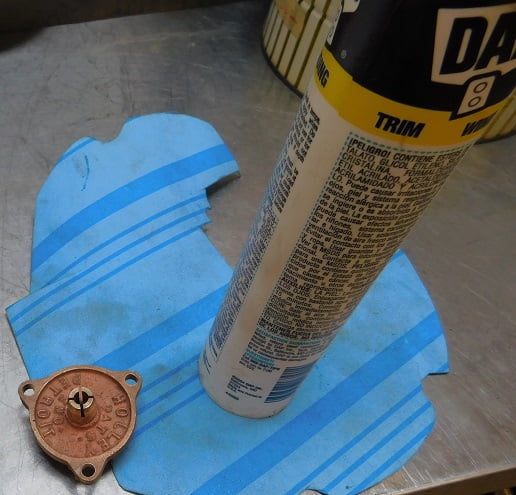
We had to make new gaskets. A piece of gasket material of suitable size was selected. A caulking tube had the appropriate outside diameter for making the mixture well cover gasket.
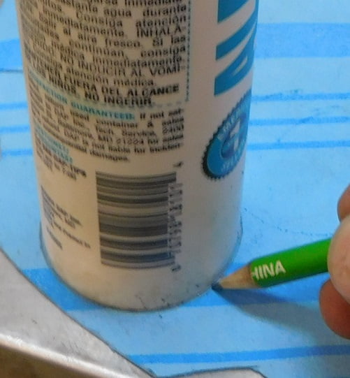
That green thing making the mark on the gasket paper is called a pencil.

The same 1 1/4″ Wards Powercraft socket that was used to remove the float bowl nut turns out to be the same outside diameter as needed for the ID of our gasket. We eyeball it to center of the first mark and use the pencil again.
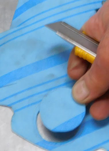
The ID of our new gasket is cut out using a razor knife.

Finally the outside diameter is cut to the line with scissors.

The float assembly is installed. The tab that contacts the fuel inlet valve must be bent to set the float to the proper dimension measured at the yellow arrows. We set it at 5/16″. With that done the carburetor can be fully assembled.
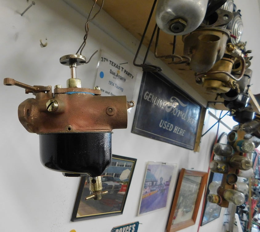
All that we need to do is test it on the car.

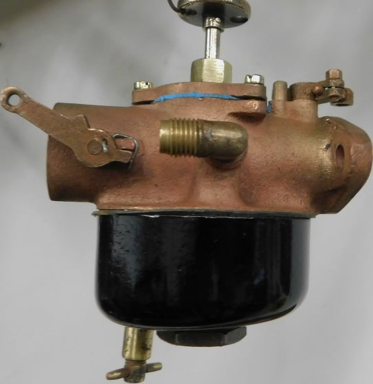

Update: we installed the carburetor. It ran OK but had symptoms of being slightly rich. We took it off and adjusted the float level to 3/8″. Success! It runs very nearly the same as it did with the previous carburetor, a Holley straight thru NH. It gets “free starts” endlessly if you turn the key off and then turn it back on within a few minutes. Great carburetor!
