Harry Miller’s factory at 6233 South Gramercy Place in Los Angeles, CA about 1926.
Harry Miller was many things. Perfectionist, engineer, designer, effete, driven, winner, dominating force, all could be used to accurately describe Miller and his products. Miller racing engines won Indianapolis and most any other race that mattered in the 1920’s. His engine designs came to be used in later years under the Drake and Offenhauser names, dominating Indianapolis through the mid 1960’s. r race that mattered in the 1920’s. Miller designed aircraft engines, boat engines, fire trucks, and of course carburetors. All were (for the most part) successful and profitable. This week we take a look at the rebuilding, installation, and performance potential of the Miller Master carburetor on the Model T Ford.
Harry Miller in 1932. Miller sold his Los Angeles based business in 1929 just prior to the stock market crash. As such he was very well off financially compared to most other Americans in that time.
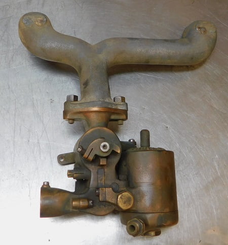
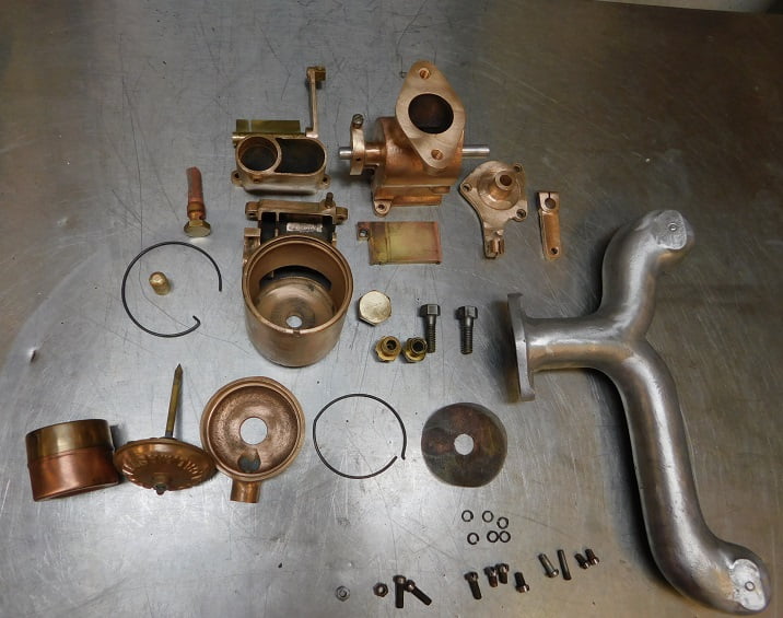
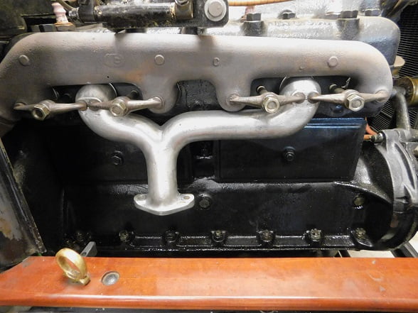
Miller built his signature carburetor design in several sizes in order to be used for many applications from racing cars to boats to fire trucks. We are going to concern ourselves with the Miller carburetor designed to be used on the Model T Ford, along with the Miller designed intake manifold that would be sold to the Ford owner as part of the installation kit.
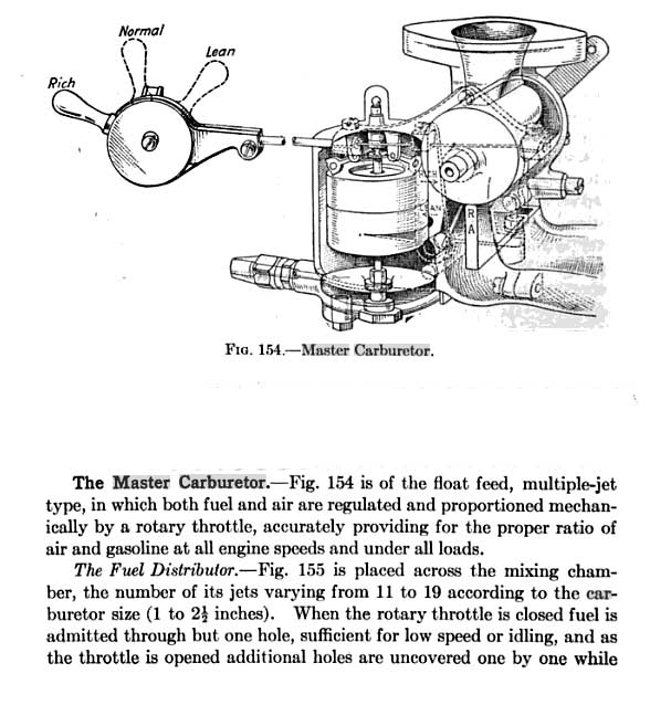
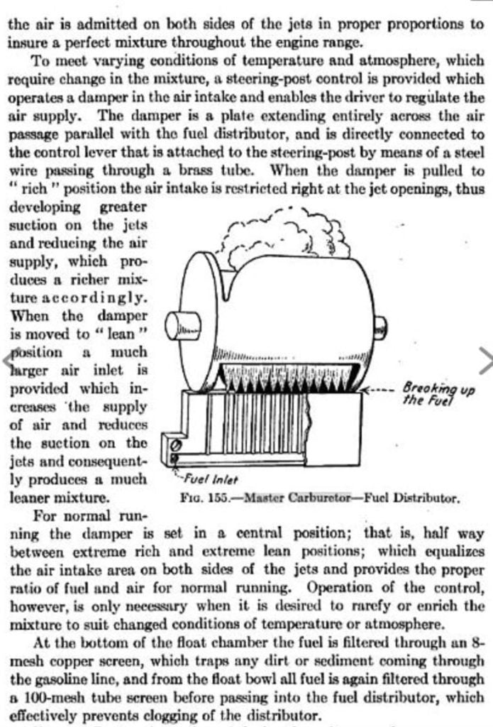
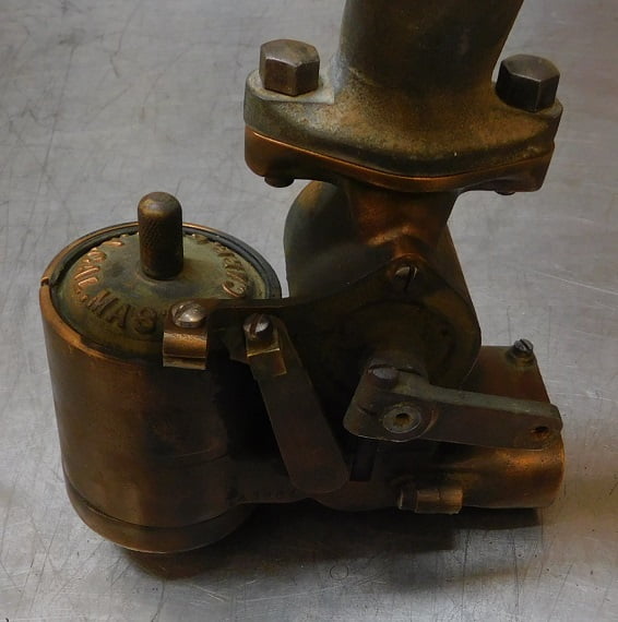
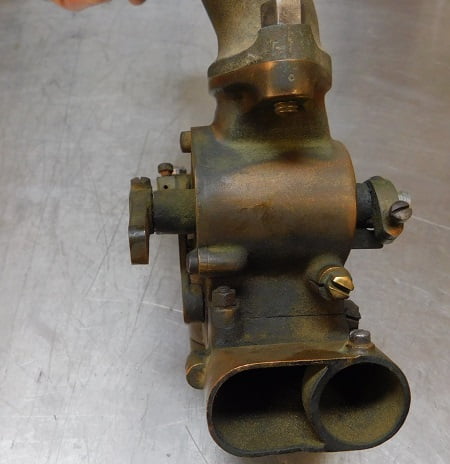
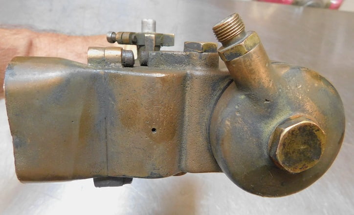
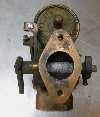
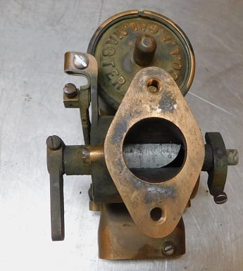
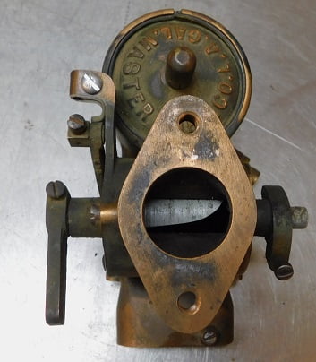
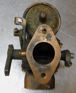
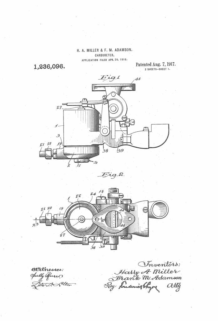
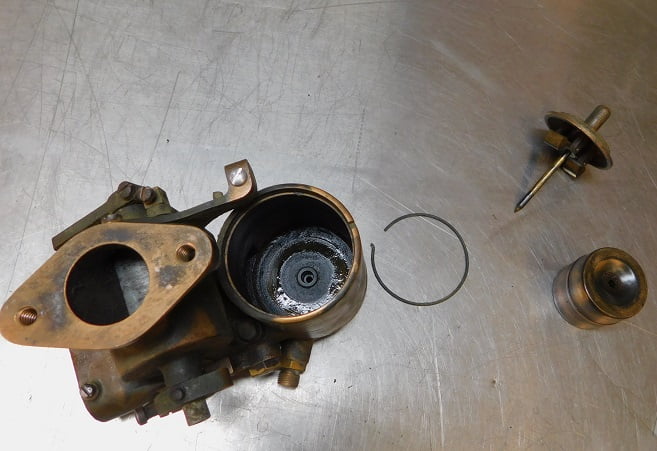
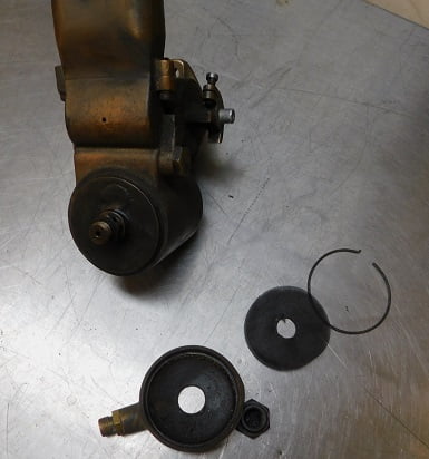
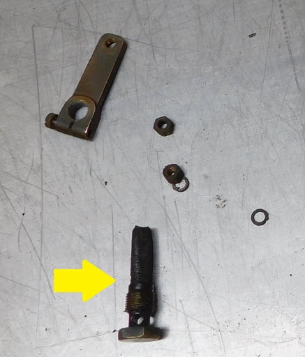
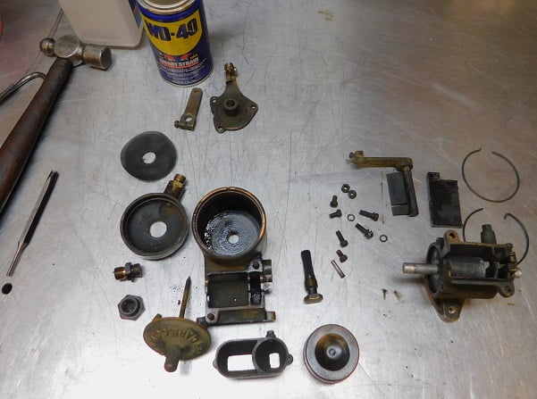
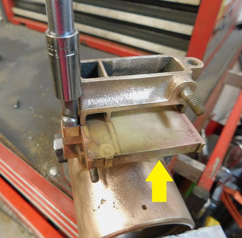
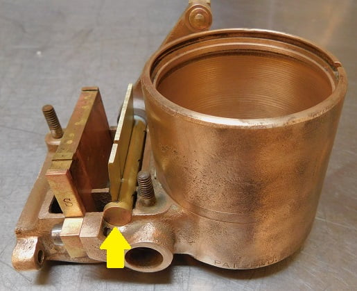
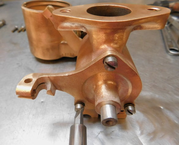
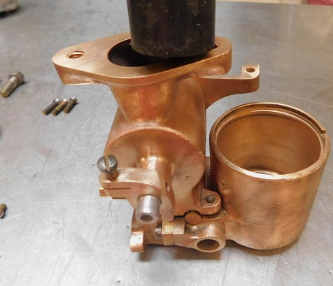
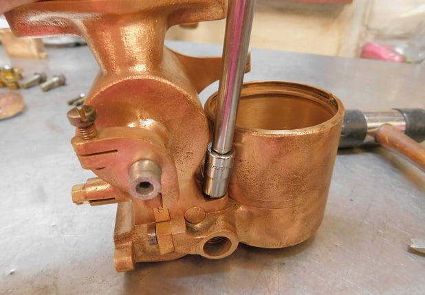
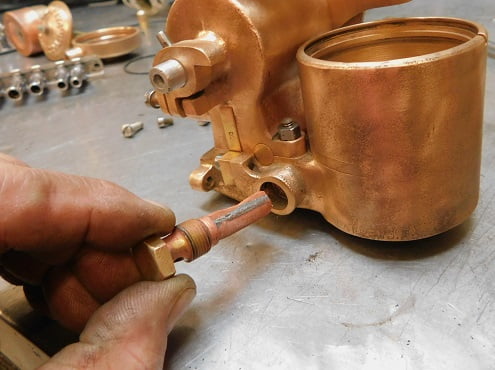
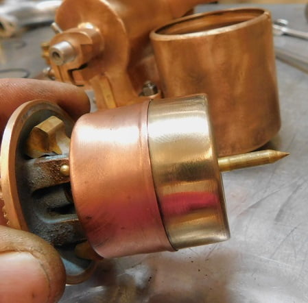
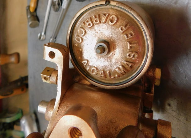
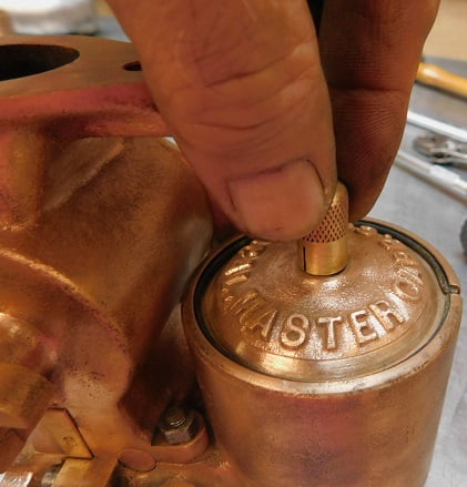
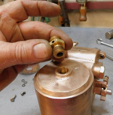
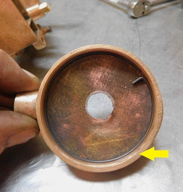
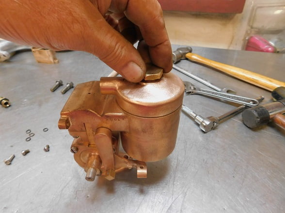
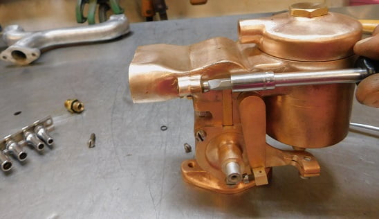
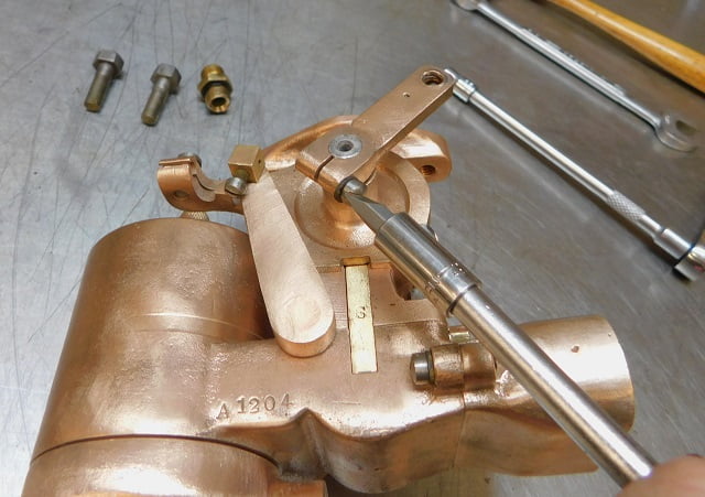
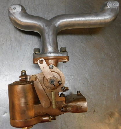
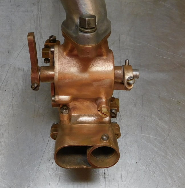
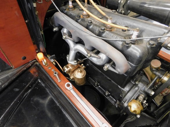
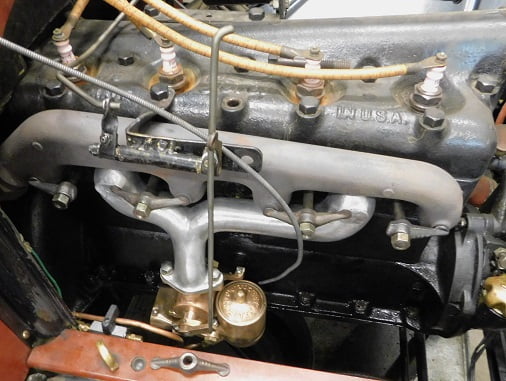
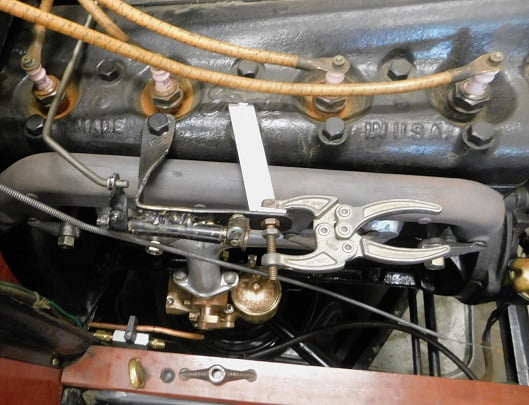
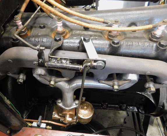
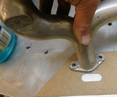
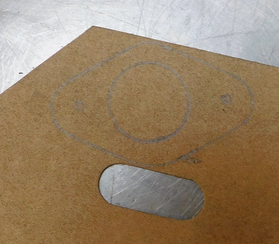
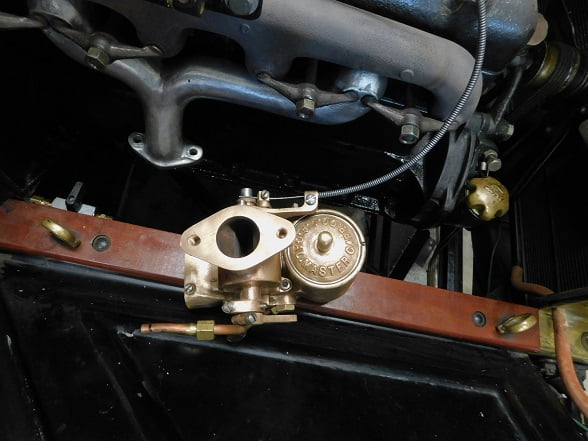
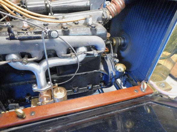
Our subject carburetor and intake were sold as a direct replacement for the Ford supplied intake and carburetor. Ours looks pretty good for being 100 years old other than a lot of grime and grease and surface corrosion. The carburetor is made from red brass and yellow brass castings. Hardware is primarily steel. The throttle valve is a barrel design made of machined aluminum alloy.Along with the intake manifold each Miller Master carburetor came with a cable operated mixture control. The mixture control operated a “damper” door inside the carburetor that blocked off much of the airflow if fully closed. This served as the “choke” for starting a cold engine. Once the engine is warm the mixture control is opened nearly all the way depending upon the engine, fuel, and altitude requirements.We found that the car ran best with the damper moved mostly, but not all the way, towards full lean. The engine side of our carburetor shows the cable operated mixture lever in the full lean position.The air inlet is separated into a primary (round) and secondary (larger, LH side) area. This design is unlike any other carburetor, as is the majority of the Miller carburetor.The underside of our Miller carburetor shows the fuel inlet which can be pointed in any direction. We ended up finding this position was ideal for a Model T.The throttle is similar to the Winfield carburetor in that it uses a barrel type throttle valve. The Miller Master throttle valve uses a graduated spiral opening that sequentially uncovers a series of fuel jets as it allows greater amounts of airflow. The photo above shows the throttle closed for idle.Here we see the throttle partly open. Notice the curved leading edge of the slot in the barrel valve.As the throttle is opened further more of the jets are exposed at the bottom of the barrel, as the top exposes more of the intake to fuel / air mixture. This makes the Miller Master carburetor very responsive.At full throttle the series of jets are entirely exposed as the intake is completely open for fuel / air mixture to flow. The barrel valve eliminates having a throttle shaft in the middle of the intake air flow.The Miller Master carburetor was patented in 1917 and could be installed in a variety of ways depending upon the application. This drawing shows the holes drilled in the fuel distributor / jet bar with the throttle wide open.We start disassembly by removing the snap ring which retains the top of the float chamber. This float / needle valve design was used by Stromberg, Marvel and other companies. We suspect someone was paying somebody royalties. Notice the accumulated dirt in the bottom of the carburetor bowl. This is good evidence that this carburetor was used a lot. Next we remove the nut which secures the fuel inlet to the bottom of the float bowl. Inside is a snap ring securing a very fine fuel filter screen that is crusted with more dirt,The upper body of the Miller Master carburetor is secured to the lower body by two nuts on studs. This one can be loosened with a socket. The other side requires an open end wrench.there is a secondary fuel filter just below the jet bar (Miller calls it a Fuel Distributor). This filter is also clogged with dirt.You can see the fuel jet bar here marked with the letter “S” attached to the lower body.We were unable to remove the throttle stop from the barrel valve despite lots of effort. In the end we decided that the better part of valor is often discretion. All of the brass parts went into the carburetor cleaning solution while the steel hardware went into a jar filled with Evaporust.After soaking for a couple days in carb cleaner each part was scrubbed using Scotchbrite and soapy water. Interestingly, Miller made this carburetor without any seals or gaskets. Each part depends upon accurate machine work to prevent fuel and air leaks. You need to be careful not to disturb any of these critical junctions.The first part to be installed is the jet bar (fuel distributor) which is secured to the lower body with a single screw. We are using a specially ground screwdriver bit in a 1/4″ drive socket to prevent marring the screws and to allow secure tightening of each fastener. The arrow points to the tiny holes that supply fuel to the air. This part is the heart of the carburetor, and is made from many pieces of brass sheet soldered together.Next the air damper / mixture control assembly is set in place in the lower carburetor assembly. It is shown in the open / full lean position.This screw interfered with movement of the mixture lever unless I removed its lock washer. It came apart that way too, so apparently it was meant to be that way originally. I removed the lock washer after this picture was taken.The upper carburetor can be mated to the lower carburetor. A few taps of the rubber mallet were required because the parts fit together so tightly. No gaskets are used, and no sealant. It just fits.We tightened the nuts. Not shown, a steel taper pin secures the throttle idle adjuster to the throttle valve shaft. We installed it using a tiny hammer.Our 1925 Dykes manual gives a nice picture of the Miller Master carburetor and its unique fuel distributor / jet plate. An elbow is mounted to the primary air inlet. It could be pointed up and connected to a heat tube for winter use, or rotated downwards and left open when it was not winter time for best performance.Fuel must pass through this secondary screen before it gets to the tiny passages in the fuel distributor. We install it and tighten it with a 5/8″ wrench. Again no gasket or seal of any kind is used.We reinstalled the float oriented as it was upon disassembly. The red brass portion is “up”. We don’t know if this matters but if it does, it won’t be a problem.The float bowl cover is held in place by a very tight fitting snap ring. It required that we tap it in place using a 3/32″ pin punch. Again, no gasket or sealant of any kind is used.A dust cap covers the top of the inlet needle. There is no adjustment and again no seal.With the carburetor upside down the fuel inlet seat can be installed. The machined surfaces simply fit, there is no gasket.The fuel inlet assembly has a very fine filter screen secured with a snap ring.The fuel inlet again has no gasket. The arrow points towards a bevel on the inside of the inlet, a similar bevel is machined into the lower carburetor body. The mating of these two machined surfaces makes a fuel tight seal with no gasket of any kind.The nut is a large 7/8″ wrench size, necessary to allow sufficient torque to prevent leakage. We ended up rotating the inlet to point towards the frame and to the rear as it had been prior to disassembly.The inlet assembly is bolted to the lower carburetor body.We tried to make the throttle work as it was when it came apart; but eventually moved the throttle arm to the other side after considering our options for linkage.Our freshly rebuilt Miller Master carburetor looks better. We hope it works as well as it looks!This view gives a good view of the taper pin that secures the idle adjuster to the throttle valve.We temporarily installed the intake and carburetor so we could figure out the controls and fuel line. We were out of steel 1/4″ diameter line so for temporary use we are going with a piece of copper that was in our scrap metal bin.A Ford Vaporizer throttle arm and connecting rod makes a great start.This bell crank assembly was left over from some previous project. With a few bends and twists it looks like it will do the job. The throttle linkage arm was moved to the outboard side of the carburetor. A piece of 3/16″ steel rod was used to fabricate the linkage rod from the bellcrank to the carburetor.A piece of 1/8″ X 1″ flat bar stock 6061 T6 aluminum extrusion was used to make a second mounting point for the bell crank.We marked the fuel line for cut off. Everything came off so we could finish the job. Every time we buy a T gasket set it comes with a long 26 – 27 valve cover gasket. Those come in handy when we need to make a gasket.Once we are satisfied with the layout we cut the gasket to shape.We reinstalled the intake manifold using fresh copper glands. The steel rings were re – used.The mixture control cable is connected before mounting the carburetor. It is hard to get to with the carburetor installed.We installed the carburetor with our new gasket. We connected the fuel line. The gas was turned on, revealing no leaks anywhere. The mixture control was set to full rich, and we pulled the crank up for two 1/4 turns. Then we turned the key on, and set the mixture about in the middle. The car started with one pull on the crank! It immediately settled into a perfect idle, although a bit slow.
Driving Impressions
Sitting behind the wheel in the garage we played with the mixture control. The engine seemed to run best with the mixture set at around 80% towards full lean. We made one more inspection to make sure there were no leaks. Then we backed out of the garage.
We had just removed a Winfield carburetor so the Master had some big shoes to fill. When this carburetor was made, Ed Winfield worked for Harry Miller. Their carburetors share some ideas such as the way the float / inlet needle design works, and the concept of the barrel throttle valve. Otherwise the designs are much different. Miller’s design is intricate and requires a lot of precision machining. The Winfield design is much simpler and it is easier to manufacture. By any account the Winfield carburetor works very, very well. Was the student better than the master?
We accelerated out of the driveway in low gear. The exhaust note was louder than before, quite a bit louder in fact. The car has markedly improved power compared to the Winfield carburetor. This is incredible because the Winfield was so exponentially superior to anything we had tried previously. Shifting into high gear, the car accelerates like never before. This carburetor may be around here for a long time. We drove around the lake for about an hour. A stop for gas was the first time we turned the engine off. After a few minutes we turned on the key and were rewarded with a “free start”. With the improved power is a certain improvement in driveability, again hard to believe because the Winfield was so good. I can’t see going back to any of the stock Model T carburetors after this. Call this a rave review if you will.
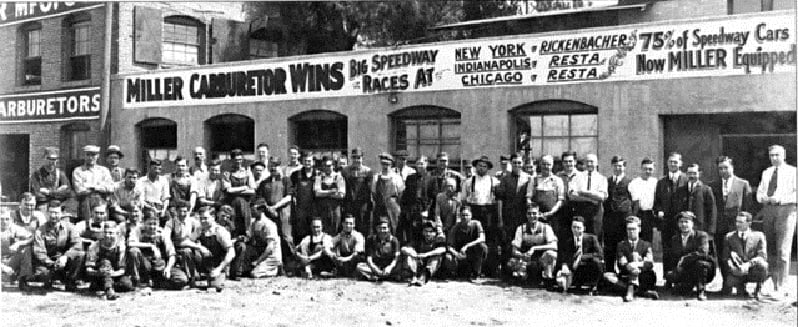
A view of the employees at Harry Miller’s shop on Gramercy Place in Los Angeles, California around 1924.