

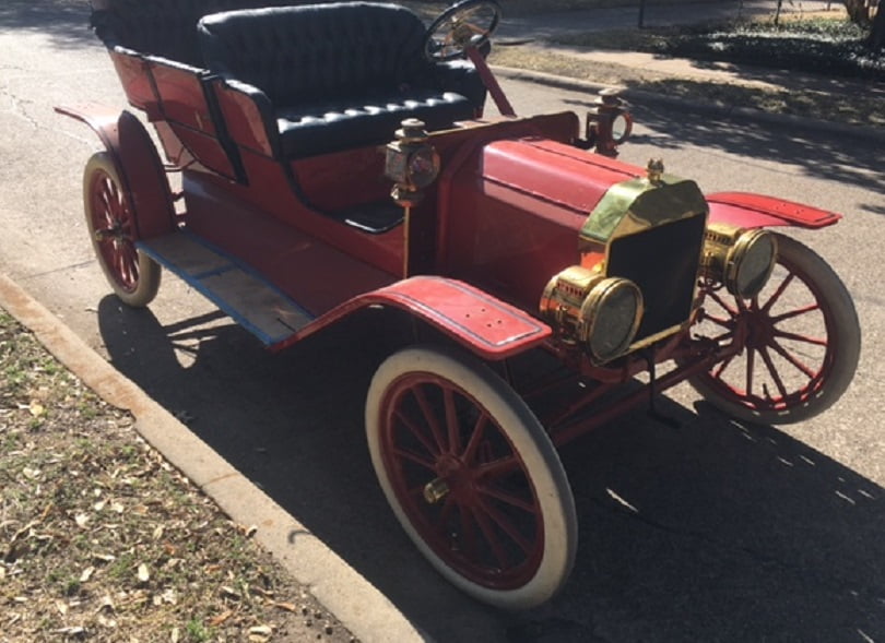
Ford built the first 2499 Model T Fords with water pumps. The brand new 1909 above is one of the first 2499 cars equipped with a water pump. The crank ratchet is made to hold the crank in either up or down position, a feature that was deleted during the redesign for all Model T’s serial number 2500 and subsequent. While the water pump idea didn’t work out for most Model T’s, it does make the earlier cars more interesting and valuable to collectors. Few were built, fewer exist, and those that do exist for the most part are never driven. The ones that are in private hands do get used, some more than others. As a result many of these cars that are driven have to be repaired frequently because the water pump design is not very good. Let’s take a look at what it takes to rebuild one.

Our subject car had always had a very leaky water pump. Various people had worked on the car over the years. It looks like they tried stop leak and other things that didn’t fix anything. Tightening the two packing nuts did not stop or even slow the leakage, in fact the only thing it did was make the engine hard to crank. On top of those issues we also noticed that very little water was being moved by the pump when the engine was running. Only one thing to do, take it apart and fix all the problems.
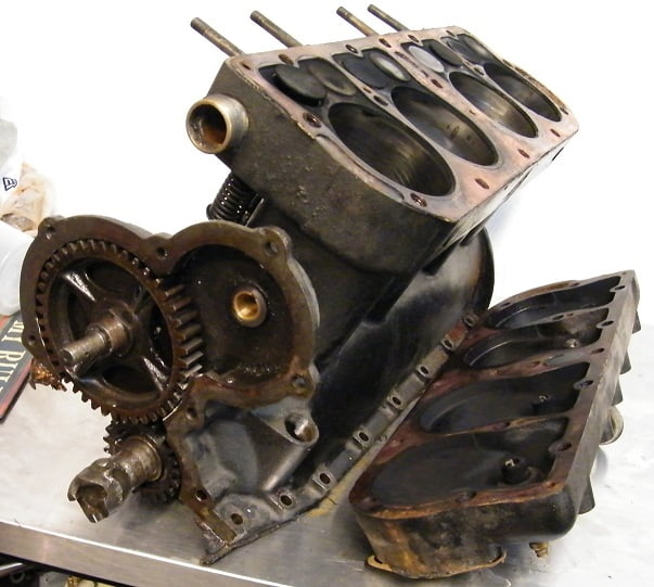
This photo and the next one were taken some years ago. The pre – 2500 Model T engine block is made differently than later Model T’s. The front of the block has a housing for the water pump drive gear, which meshes with the camshaft gear. The net result is that the water pump runs at engine speed since the cam is turned at 1/2 engine speed and the water pump is driven at twice cam speed.
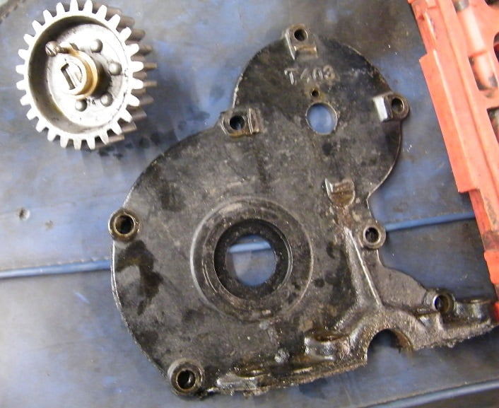
Above the water pump drive gear and its bearing, both of which live behind the engine front cover. The water pump drive bearing bolts to the engine front cover with a single screw. Three bolts secure the water pump to the front cover. We removed the water pump from the engine after loosening the pack nuts on the inlet (radiator end) and outlet (at the engine block).
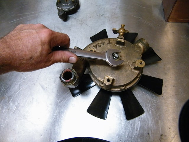
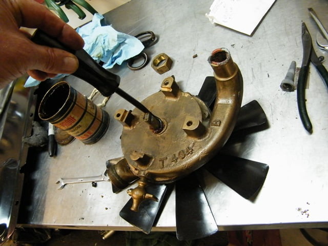
We cleaned off all the sludge and grime before starting to disassemble the pump by first removing the rear packing nut. Note that the front and rear packing nuts are not interchangeable. One is reverse (LH) thread, the other is normal (RH) thread due to the direction of shaft rotation.
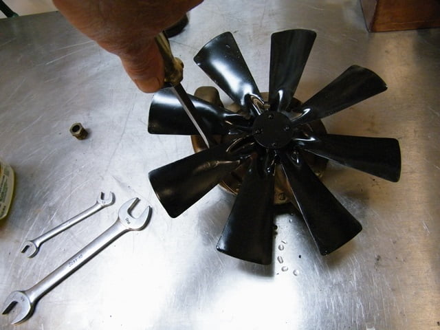
After removing the rear packing nut we can take out the screws which secure the two halves of the pump to one another.
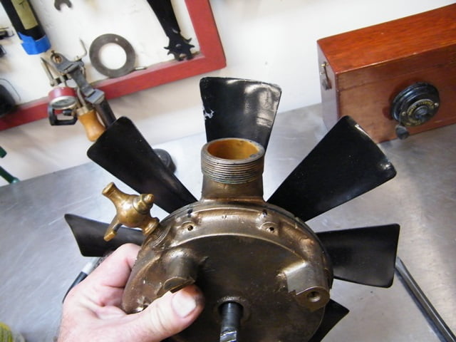
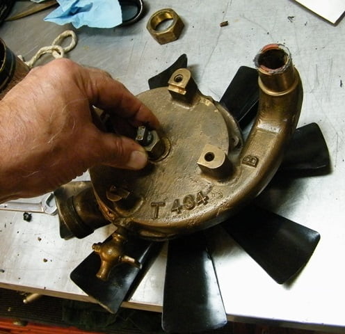
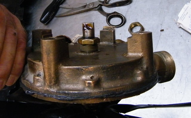
We took this photo to record the proper position of the petcock when we reassemble the pump halves later. The rear half of the pump can be removed.
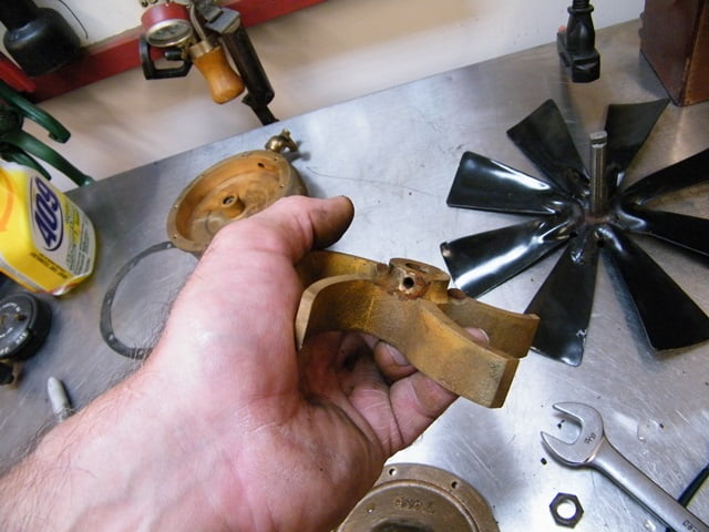
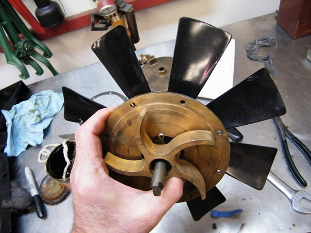
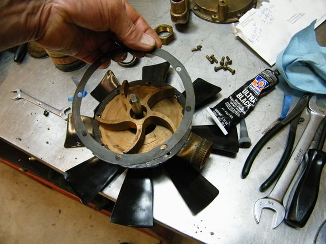
Normally the next step is to remove the cotter pin which secures the impeller to the water pump shaft. In our case when we took the rear cover off the impeller would spin freely on the shaft, and we pulled it right off. There were remnants of the steel cotter pin. It had rotted away, leaving the shaft disconnected from the impeller. This tells us why there was so little movement of water. Also, there was no packing material under the pack nuts which explains the profuse leakage.
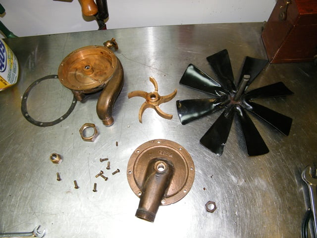
The water pump parts are all cleaned and prepared for assembly.
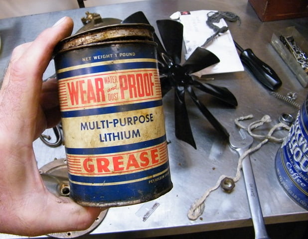
WE have a can of water pump grease that is designed specifically for this application. If you don’t have any the next best thing is a good red synthetic grease such as Mobil 1.
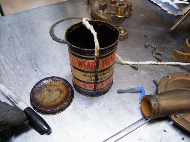
1/4″ Asbestos water pump packing string is passed through the grease. We estimated that 3″ would be needed for each end of the pump. We cut it with scissors after it had grease on it to eliminate the possibility of creating airborne asbestos fibers which can be very hazardous.
The packing nut is slid onto the water pump shaft then the grease impregnated string is wrapped around the shaft before inserting everything into the front pump body. Note that the front packing nut is reverse (LH) thread.
With the parts assembled the nut can be tightened until resistance is felt to rotation of the fan / shaft.
The impeller is secured to the shaft using a stainless steel cotter pin.
We used the old gasket to make a pattern for the new one. Silicone sealant was placed on both surfaces of the pump housing before assembly. We aligned the two halves to place the inlet / outlet and petcock properly, then installed the screws.
We wrap the grease impregnated packing string around the shaft and then stuff it into the rear seal cavity using a cotter pin removal tool.
The packing nut is installed and tightened. Again you want to tighten the nut just enough so that you can start to feel a slight resistance when turning the fan.
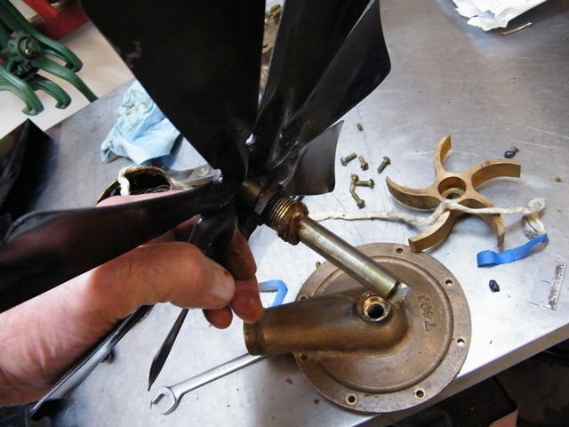
The drive shaft is aligned so that it fits into the drive gear slot when the pump is reinstalled. A bit of grease is placed on the drive shaft to prevent wear. Not shown, we installed the inlet and outlet packing nuts using a bead of silicone sealant instead of more grease infused asbestos.
With our pump reinstalled and the radiator filled to about 4″ below the top with coolant the only thing left was a test drive. We had no leaks for the first time ever! From a maintenance standpoint the water pump needs to be removed and repacked with grease perhaps every 500 miles because the grease eventually will leak out around the shaft.