
This week we are blessed to have a very instructive article written by Ron Patterson and Bob Cascisa.
Over the years I have had the opportunity to help many with Model T electrical system problems. I discovered that many Model T Fords were incorrectly wired. In some cases those cars were being driven and the owner thought everything was working correctly. I quickly ceased believing anything anyone told about their car and developed some simple tests that will validate if the wiring is correct so one could rely on the dash Ammeter to provide reliable data when looking for problems.
I suggest you first read the article “Model T Ford Battery Charging System” to fully understand how the charging system operates. This article can be found
Here in the Model T Ford Fix website (modeltfordfix.com).
The basic function of the Model T Ford Charging System is to maintain the Battery at a proper level of charge to provide sufficient electrical power for the starting motor, ignition and headlamps while providing an Ammeter indication the system is working properly. The Ammeter indicates the net power in the electrical system. If it indicates a Charge, the generator is providing sufficient power to meet the electrical demands (Ignition and lights) and to keep the Battery charged. If it indicates a Discharge, the Generator is not providing enough power to carry the load and keep the Battery charged. A dead or weak Battery will result by driving the car with the Ammeter continually showing a discharge condition.
When working on Model T wiring it is important to be sure you are using a correct wiring schematic. Many commonly available wiring schematics are incorrect, particularly in the charge/discharge circuit wiring. Additionally, many reproduction dash Ammeters do not have their polarity clearly marked + or – on the terminals and as a result is commonly wired incorrectly. These wiring errors can allow the Ammeter to show only discharge current and no charge current or vice versa. I recommend you use the wiring schematic in Figure 1. This wiring schematic is electrically correct for the starter-generator equipped Model T.
Here is an easy way for anyone with limited electrical knowledge to functionally check the charging system and correct any trouble.
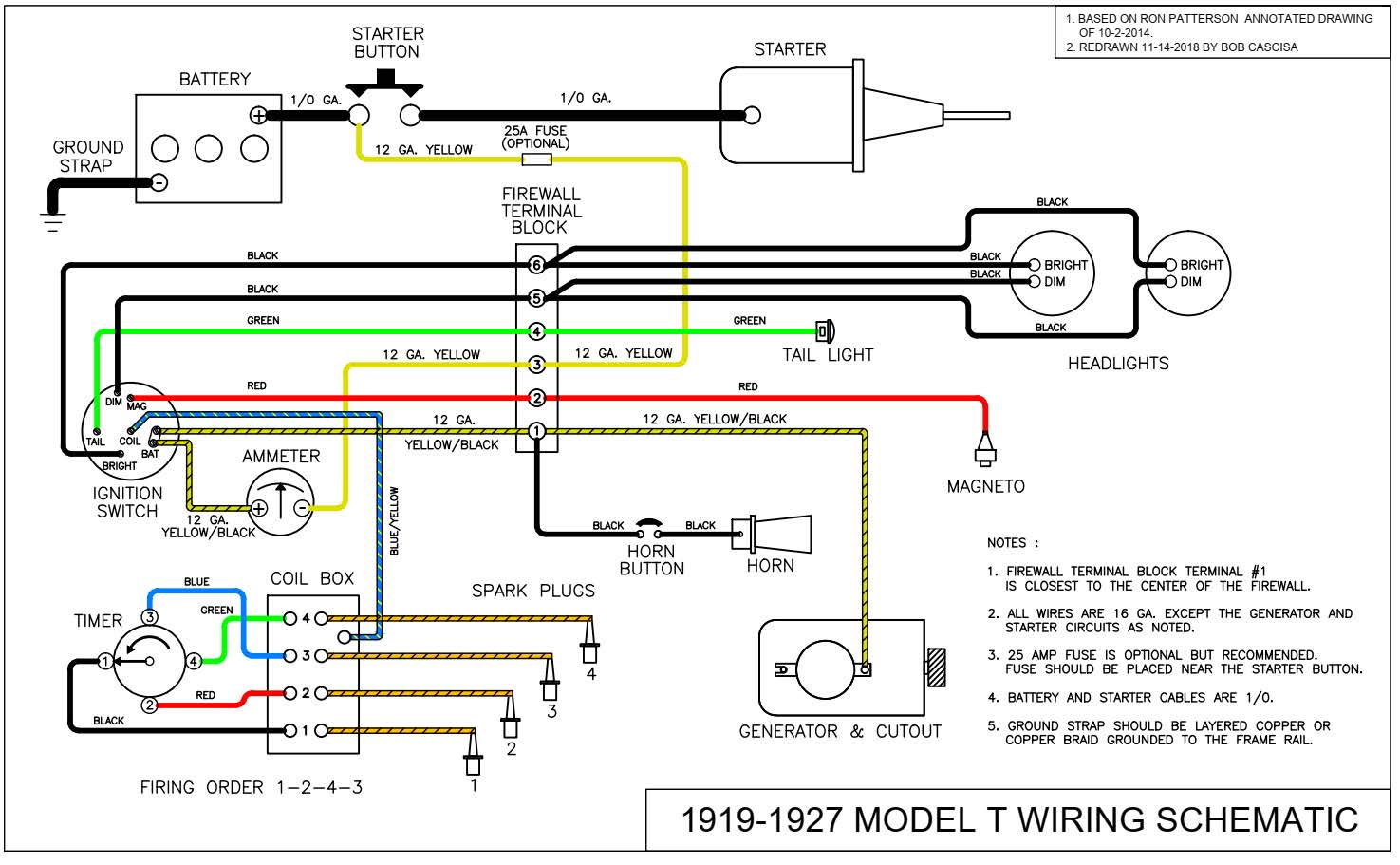
Figure 1. Shows all electrical wiring including the details of the Generator, starting motor, ignition, horn and lamp load circuits. The charging system has only five wires and is designed to carry 20 amps of current. Note – Originally there was no fuse.
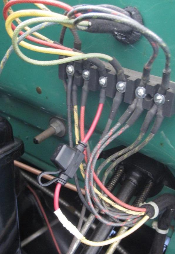
Figure 2. Typical fuse installation
The installation of a single 25 Amp fuse (above) is highly recommended and will provide adequate safety protection for all the original circuits in a Model T. This fuse should be installed in series with the Yellow wire 5 (Figure 3) between the starter switch and the firewall terminal block terminal 3. You can use either a replaceable 25 Amp cartridge or ATC type fuse. Figure 2 shows a commonly available water proof ATC fuse holder installed in a Model T Ford.
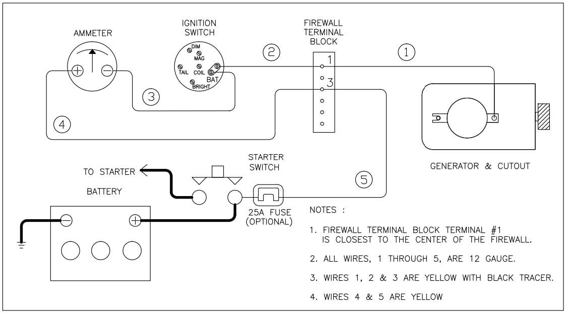
Figure 3. Battery Charging System Physical Wiring Diagram
Figure 3 is a simplified Battery Charging System physical Wiring diagram. There are five charging circuit wires numbered 1 to 5 and encircled. The actual wires do not have numbers on them. The proper color code for each of these 12 gauge wires is indicated in Notes 3 & 4. The Generator, cutout, firewall terminal block interconnecting points (terminals 1 and 3), rear of the ignition switch, Ammeter, starter switch and Battery are shown. The lamp loads are connected to the Bright, Dim and Tail terminals. The lamp loads are controlled by the light switch lever on the dashboard. The ignition load is applied when the key is in the BAT position. If a Battery horn is installed it is connected to terminal block terminal 1. In many cases you will find wire 3 is a 14 or 16 gauge wire. If this is the case it should be replaced with the correct 12 gauge wire.
Initial Checks.
When the engine is not running and the headlamps are turned off the Ammeter needle should be at the center of the scale “0” and should not indicate any charge or discharge. If it does, it is important to find out why this is occurring because it will ultimately fully discharge the battery. If there is any charge or discharge shown on the Ammeter the cause must first be ascertained and corrected.
Test 1. Verifying the Generator DISCHARGE Circuit.
The Discharge circuit is the loads that are placed on the Generator. Headlights, ignition coils and the battery are seen as loads by the generator. In this test we will apply a load to the Discharge Circuit. The Ammeter should deflect to the left showing a discharge indication.
- The engine will not be running for this test.
- Turn on the headlamps.
- The Ammeter should deflect to the left showing a discharge.
- Turn off the headlamps.
If the Ammeter needle deflects to the right (Charge) in step 3 above, the Ammeter is wired backwards. To correct this, reverse the two ammeter wires. Remember many aftermarket and reproduction Ammeters do not have any or correct ( + ) and ( – ) markings at the terminals.
Test 2. Verifying the Generator CHARGING Circuit.
The Charging circuit delivers the charge current from the Generator to the Battery. In this test we will momentarily short the Charging circuit wire to ground. To conduct this test you will have to remove the previously discussed 25 amp fuse if installed and short across the two fuse terminals with a 12 gauge wire. During this test the Ammeter should momentarily deflect to the left showing a maximum discharge indication.
- A helper may be needed to watch the Ammeter while conducting this test.
- The engine will NOT be running during this test.
- Remove the Yellow with Black tracer wire from the cutout output terminal.
- Momentarily (NOT MORE THAN 1 SECOND) touch this wire end to the exhaust manifold (you will see a spark).
- The helper should see the Ammeter needle move to the far left, showing a Discharge.
- Reconnect the wire to the cutout.
- Reinsert the fuse if installed.
If the needle shows no deflection in step 5 (remains centered at “0” amps) the Yellow wire #2 is probably wired to the ( + ) side of the Ammeter as opposed to the Bat terminal on the switch. Make sure wires #2, #3 and #4 are wired exactly as shown in Figure 3.
Upon successful completion of these two tests, the Charge and Discharge circuits are verified to be wired correctly.
If these tests are not successful it may be necessary to trace the charge circuit wires point – to – point. Table 1 (below) is provided to help this effort.
Table 1. Generator Circuit Point to Point Wire List
| Wire Number (Fig. 2) | Wire Color & Size | Description |
| 1 | Yellow / Black Tracer 12 Gauge | From : Cutout output terminal on the Generator To : Firewall Terminal Block Terminal 1 Note : Terminal 1 is closest to the center of the firewall |
| 2 | Yellow / Black Tracer 12 Gauge | From : Firewall Terminal Block Terminal 1 To : Ignition Switch BAT Terminal Note : It can be connected to either BAT Terminal |
| 3 | Yellow / Black Tracer 12 Gauge | From : Ignition Switch BAT Terminal To : Ammeter NEGATIVE ( – )terminal Note : No other wires should be on the Ammeter ( – ) terminal |
| 4 | Yellow 12 Gauge | From : Ammeter POSITIVE ( + )terminal To : Firewall Terminal Block Terminal 3 Note : No other wires should be on the Ammeter ( + ) terminal |
| 5 | Yellow 12 Gauge | From : Firewall Terminal Block Terminal 3 To: Starter Switch Terminal. Note: An optional Fuse may be installed in this wire near the Starter Button. Note: The heavy wire from the battery Positive terminal is also connected here. |
Another Common Wiring Error
You may discover another physical wiring error that appears quite often.
- As you can see from Figures 1 and 3, there should be only one wire on each terminal of the Ammeter.
- It is common to find Figure 3, wire 2 from firewall terminal block terminal 1 wired directly to the Ammeter “-“(minus) terminal and not the ignition switch BAT terminal.
- Although this looks electrically equivalent, it is not physically correct.
- To correct this simply move the end of wire 2 from the Ammeter “-“ (minus) terminal back to the BAT terminal on the ignition switch.
- There should be two wires (Figure 3, wires 2 and 3) on the ignition switch BAT terminal.
- Although this wiring method will allow the headlamps and ignition circuits to work it is physically incorrect.
At this point a general word about Model T Ford Ammeters is in order. There were many different manufacturers of original Model T Ammeters. Most of them were cheaply made and are notorious for their inaccuracy. The cheap reproduction Ammeters available today are not much better. There is one bright spot on the Ammeter scene. Fun Projects manufactures and sells an accurate reproduction Ammeter for the 1919-1925 Model T’s shown in Figure 4. This Ammeter uses a high quality D’Arsonval meter movement that is very accurate. They are more expensive, but it is well worth the extra cost. There is currently no quality reproduction Ammeter available for the 1926/27 Model T’s being manufactured or sold.

Figure 4. Test Ammeter
If you commonly work on Model T electrical problems you may want to consider making up a simple trouble shooting test Ammeter. Figure 4 shows one I made that uses 12 gauge wire, has insulated alligator clips and can be temporarily wired in series with the Yellow wire #5 in Figure 3 (similar to the fuse shown in Figure 2.) for obtaining accurate readings while trouble shooting electrical troubles. The hooks are for hanging it on the radiator support rod during use.
Battery, Generator an Cutout trouble shooting
As a result of the tests and corrective action taken above, the car should be wired correctly and we can address the other parts of the charging system that could be causing trouble. Those system elements are the Battery, Generator and Cutout.
Checking a 6 Volt Battery
To ensure your Battery is in good health, using a trickle charger, charge the battery overnight. Remove the charger and let the battery sit at room temperature of 12 hours. Then check the battery voltage with a voltmeter and it should read between 6.3 and 6.4 volts DC. This is Voltage reading of a fully charged 6 volt battery at room temperature. If it does not show 6.3-6.4 volts after charging and resting for 12 hours the battery is in poor health and should be replaced.
Use caution when buying a new 6 Volt Battery. Take your voltmeter along and check the Battery you plan to buy to ensure it reads between 6.3 and 6.4 Volts. If it does not read this voltage try another Battery and find one that is fully charged. Be sure to check the manufacturing date code on the Battery case to ensure it has not been sitting on the shelf for an extended period of time.
If the Ammeter is not showing a charge when the engine is running at moderate speed the Battery will not be charged and will ultimately become partially or completely discharged. This is a dangerous situation because if left in a discharged state for very long period the Battery will be permanently damaged and cannot be saved by recharging…
Common Generator problems
This section assumes that the car has an original reverse current relay or internal diode type Cutout installed on the generator. While these two devices work internally different, the indications and test procedures are the same.
| Caution Do not use the following test procedures on a generator equipped with a Fun Projects Voltage Regulator. Permanent damage to the VR will result. |
When Generator and Cutout are working correctly and the engine is first started, the generator increases its output to a normal operating level. This internally controlled automatic generator start up process it called “building up.” When the generator output voltage reaches 7.2 volts (the normal charging voltage of a 6 volt battery), the contacts in the cutout close connecting the Generator to the battery.
The Ammeter will show the amount of charge the Generator is producing. If the Ammeter does not show a charge after engine start up and running at medium speed here is a simple test to determine if the Generator is not “building up” and starting to charge. This procedure is sometimes referred to as “Flashing the Field.”
- The engine must be running for this procedure.
- Using a short length of wire momentarily short between the Generator output terminal and the Cutout contact where the Yellow/Black wire is connected (there may be a spark).
- Look at the Ammeter and see if it shows the Generator is charging.
- Remove the jumper wire.
- If the Generator now shows a charge, shut the engine off and restart it.
- See if the Ammeter now shows a charge.
- If the Ammeter does not show a charge, repeat steps 1 – 4 above.
- If Ammeter still does not show a charge the Cutout may be defective.
Try replacing the Cutout with a good quality replacement or a good quality internal diode type. If after replacing the Cutout this problem persists the most likely cause is the Generator is not “building up” on its own, this is a common generator fault and has several possible causes.
A buildup of carbon dust from the Generator brushes mixed with oil can created a short inside the Generator. The armature commutator is fouled with a coating of this dust causing poor brush contact. Both of these conditions can affect the ability of the Generator to “build up” and start charging. Cleaning the internal Generator brush area with some contact cleaner and sanding the commutator to remove any carbon build up may help.
If when shorting across the Cutout the Ammeter shows a large discharge then the Generator has an internal short and likely needs complete rebuilding. One additional generator test is to start the engine,
run at medium speed and measure the voltage at the Generator terminal bolt. If no voltage is present the Generator is not working and likely needs complete rebuilding.
WARNING about the Model T “third brush regulation” type generator.
When the Cutout fails to operate or there is no Battery connected, the third brush” building up” process continues uncontrollably. The armature voltage increases to 20+ volts and there is no load on the armature output to absorb the current being produced. A great amount of heat is produced in the armature and field windings and it becomes a race to see which fails first to stop the “building up” process. The field windings can simply burn out or the solder in the commutator segments, where the windings connect, melts and is found thrown around the inside of the generator case. This is one of the biggest downside risks of the third brush regulation generator design.
Common Cutout Problems
When the engine is not running and the Ammeter shows a continual approximate 6 Amp discharge and is warm to the touch, the Cutout contacts are stuck closed. If this condition is not corrected the battery will be very totally discharged in a short period of time.
In the long term, the reverse current Cutout commonly fails from the constant opening and closing of the contact under high current conditions. If you can find one, the good quality reverse current Cutouts made in USA from 1920-1950’s will work reliably for a long time. But, the very poor quality overseas made reverse current Cutouts sold by antique parts suppliers today are almost useless and will only last a short period of time.
There are two other good choices to replace the troublesome reverse current relay type Cutout. There exist at least two good quality Diode replacement cutouts for sale by Model T parts suppliers. Another good cutout replacement solution is the Fun Projects Voltage Regulator. This device modulates the Generator output to the extent it senses when the Battery needs recharging. This is an excellent choice that makes things very easy on the marginal Model T Generator and Battery charging system. You cannot troubleshoot a malfunctioning charging system with a Voltage Regulator installed. Instead, use a known good Diode type replacement Cutout.
Setting the optimal Generator charging rate
During the Model T era drivers operated their cars on short trips and at low speeds. To keep the Battery fully charged it was necessary to set the Generator to the Ford recommended 10-12 Amps charging rate. This situation is not the case today; Model T’s are driven at higher speeds and on longer trips.
The Model T Generator has a sustained capability to produce 100 Watts of power. This means you should keep the charging rate as low as possible and still keep the Battery fully charged. Under normal driving conditions the Generator charging rate only needs to be set for 5-7 Amps. The 5 Amp rate is optimal to keep the Battery fully charged. If you drive a lot at night with headlamps you may find the 7 Amp rate better for keeping the Battery fully charged. After starting the engine it only takes a few minutes to replace the current used by the starting motor. Warning – Setting the charging rate too high will require constantly checking and replenishing the Battery water. If the battery is consistently overcharged it can explode.